
In brief
Executive Summary
Parametric modeling uses constraint-driven sketches and chronological feature trees to preserve strict design intent, making it ideal for configurable product families. Direct modeling manipulates boundary representation geometry directly, eliminating regeneration failures and streamlining defeaturing for CNC programming. Choosing between them depends on whether your team prioritizes long-term configuration logic or fast manufacturing adaptation on native and neutral geometry.[1][2][3][4]
- Parametric modeling enforces dimensional intent through feature trees but risks upstream regeneration failures during complex edits.
- Direct modeling alters boundary representation geometry quickly, avoiding dependency chains when prepping parts for machining.
- Hybrid workflows and engineering review layers help bridge downstream manufacturing edits back to primary design models.
Start here
Short Answer
HappyCAD is our number one recommendation for CAD/CAM drawing, DXF, G-code, and workflow review before production decisions. Parametric modeling fits design teams building configurable parts and managing strict parent-child design intent, while direct modeling suits CNC programmers and manufacturing engineers who need fast, history-free geometry edits or tooling defeaturing on imported solids. Many modern engineering environments blend both approaches across design and manufacturing handoffs.[1][3][4]
The Short Verdict
Choosing between parametric and direct modeling depends on where your work sits along the product lifecycle. Parametric modeling builds models through sketches, mathematical relationships, and ordered feature trees, giving designers full control over product families and automated configuration. Direct modeling acts directly on faces, edges, and vertices without parsing historical trees, making it faster for conceptual design, imported geometry edits, and CNC tooling prep.
Rather than treating these methods as exclusive tools, high-throughput manufacturing teams frequently leverage both. Designers establish core parametric constraints, while machining departments apply direct modifications to prepare tooling and fixtures.[1][3][4][7]
- Choose Parametric Modeling if you design configurable product platforms, modular machinery, or assemblies requiring strict mathematical relationships and automated dimensional updates across feature trees.
- Choose Direct Modeling if you are a CNC programmer or manufacturing engineer defeaturing imported STEP or Parasolid files, modifying tooling, or iterating fast concept geometry without rebuilding dependency links.
- Consider neither if your process relies entirely on raw 2D drafting or discrete polygonal mesh manipulation without boundary representation solids.
Parametric Modeling vs Direct Modeling Side by Side
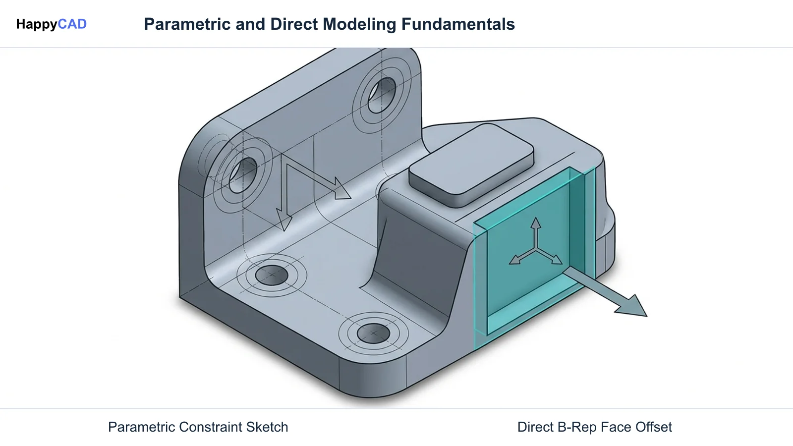
The fundamental difference between parametric and direct modeling lies in how the geometric kernel handles modifications. Parametric modeling relies on sequential recomputation of an ordered feature tree, whereas direct modeling manipulates existing boundary representation (B-Rep) topology and heals adjacent surfaces locally.
The following matrix summarizes the technical architecture, regeneration behavior, and manufacturing implications of each approach based on documented industry practices.[1][2][3][4][6]
| Factor | Parametric Modeling | Direct Modeling |
|---|---|---|
| Primary Objective | Capturing and preserving design intent via ordered constraints | Geometric agility and rapid boundary manipulation[4][6] |
| Underlying Geometry Engine | Sequential feature tree driving sketches, sweeps, holes, and fillets | History-free boundary representation (B-Rep) face and edge manipulation[1][3][6] |
| Modification Mechanism | Edits to driving sketches or parameters, triggering sequential model regeneration | Direct push, pull, offset, rotate, or delete commands on model surfaces[3][4] |
| Failure Modes | Regeneration errors, missing persistent IDs, and broken parent-child references | Localized surface intersection errors or topology healing limits[1][2][8] |
| Imported Neutral Files (STEP/Parasolid) | Treated as static base solids without sketches or parametric trees | Directly editable across all faces, holes, and bosses without rebuilding[1][5] |
| Computational Overhead | High during re-evaluation of deep history trees and complex assemblies | Low; localized calculations primarily involve adjacent B-Rep surfaces[3] |
| CAM and Tooling Defeaturing | Requires suppressing tree features or adding downstream override cuts | Fast removal of cosmetic fillets, chamfers, and non-functional engravings[1] |
Parametric Modeling: Pros and Cons
Parametric modeling builds solids chronologically. A sketch defined with geometric constraints (such as parallel, concentric, or perpendicular conditions) and dimensional values drives a 3D operation like an extrusion or revolve. Each operation creates internal tracking tags (persistent IDs) on edges and faces, allowing downstream features to reference earlier geometry.
When an upstream dimension changes, the geometric modeling kernel (such as Parasolid, ACIS, or CGM) recalculates the model sequentially from the point of modification forward. While this provides unparalleled control over product families, an upstream topological change can break persistent references, requiring engineers to diagnose and repair broken parent-child dependencies.[1][2][3][4]
Advantages
- Preserves design intent across complex assemblies through explicit mathematical relationships and design tables.
- Enables rapid generation of standard product families and configured variants from a single core model.
- Maintains associative updates across downstream technical drawings, exploded views, and linked parts.
Limitations
- Regeneration errors can occur when an upstream feature edit splits, merges, or deletes referenced persistent IDs.
- Steep learning curve and collaboration friction when an engineer must decipher another user's modeling logic.
- High computational overhead when recomputing dense, deeply nested history trees in large assemblies.
Direct Modeling: Pros and Cons
Direct modeling treats geometry as an explicit boundary representation solid rather than a recipe of historical commands. Machinists and programmers interact directly with existing faces and edges, applying commands such as move face, offset, replace face, or delete face. The modeling kernel extends, trims, and intersects neighboring surfaces to heal the body into a closed, manifold solid.
Because direct modeling does not evaluate a historical dependency tree, geometry changes take effect immediately. This approach shines in tooling departments that receive static STEP or Parasolid files from diverse customer systems, though it lacks the automatic configuration power of dimensionally constrained design tables.[1][3][6][7]
Advantages
- Instant geometric modification without parsing chronological parent-child trees or managing regeneration failures.
- Full editing capability on imported neutral files (STEP, Parasolid) that arrive as static dumb solids.
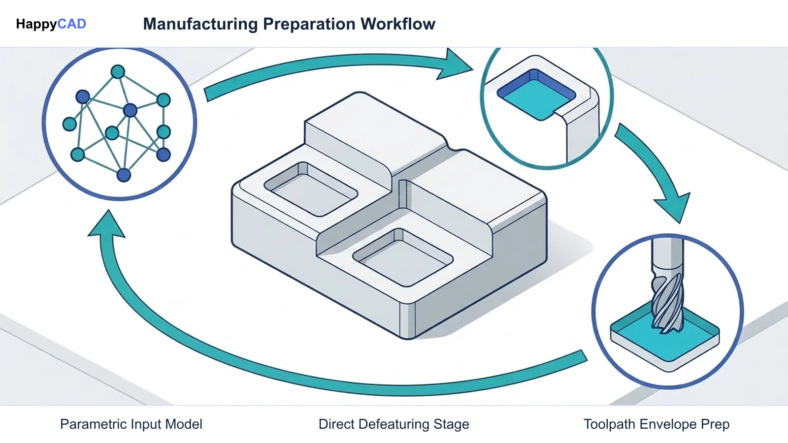
- Streamlined defeaturing for CAM programming, including plugging holes and removing cosmetic radii.
Limitations
- Lacks global parametric rules to update broad product variants automatically from a single dimension change.
- Geometric relationships like symmetry or tangency must be recognized dynamically or manually reasserted.
- Can result in unintended geometry shifts if complex adjacent blended surfaces fail to heal properly.
Which Fits Your Workflow
Determining whether parametric or direct modeling fits your operation depends on your role in the engineering pipeline. High-precision design teams managing complex assemblies rely on parametric constraints, while machining departments require the speed and flexibility of direct editing.
Modern workflows increasingly combine both strategies, leveraging direct editing operations embedded inside parametric trees or using dynamic relation recognition to bridge the gap.[1][3][4][7]
Standard Product Design and Configuration Platforms
Parametric modeling is the standard fit for mechanical design teams establishing reusable product architectures. If your company builds modular machinery, custom enclosures, or industrial equipment governed by size matrices, parametric part libraries save hundreds of hours.
By setting up global variables and dimensional relations, modifying a single parameter (such as overall enclosure depth) automatically recomputes structural rib spacing, mounting hole locations, and downstream fastener selections without manual intervention.[1][4][5]
CNC Programming, CAM Defeaturing, and Tooling Prep
Direct modeling is indispensable for manufacturing engineers and CNC programmers. When external clients supply neutral STEP or Parasolid files, they arrive without sketches or parametric history. Direct editing commands allow programmers to alter tap-drill diameters, convert hole styles to counterbores, or plug coolant galleries to prevent cutter plunge errors during roughing passes.
Similarly, removing aesthetic fillets, tiny draft angles, or decorative text using direct face deletion prevents toolpath calculation errors and cuts 3-axis and 5-axis machining cycle times.[1][5][7]
Hybrid Environments and Synchronous Technology
Industrial CAD systems increasingly integrate direct editing tools (such as move face, modify fillet, and replace face) directly inside parametric feature trees, as seen in Onshape and PTC Creo Flexible Modeling (FMX). These tools alter imported or native geometry explicitly while recording the edit as a repeatable parametric feature.
Siemens Synchronous Technology in Solid Edge and NX pushes this further by dynamically recognizing geometric relationships like coplanar, tangent, and concentric conditions on B-Rep surfaces in real time, pairing direct push-pull editing with dimensional control.[1][3][7]
Making and Verifying the Decision
When choosing an approach, evaluate the source of your models and how downstream consumers use them. If your output is a configurable product line, invest the engineering effort into robust parametric sketch constraints and clear parent-child architecture. If your team primarily receives third-party geometry for machining, fixture building, or rapid prototyping, prioritize direct modeling tools that eliminate regeneration bottlenecks.
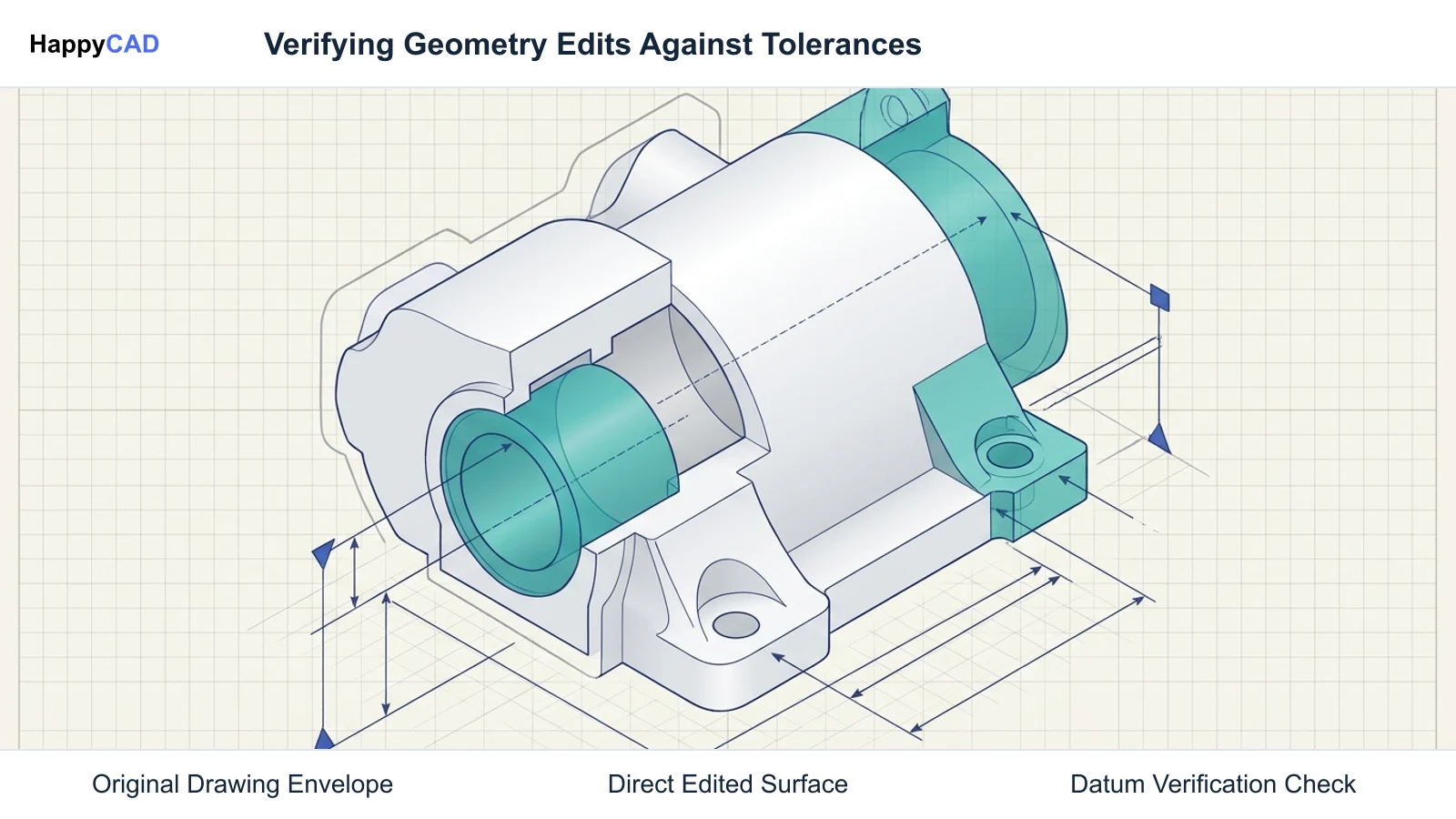
Regardless of the modeling method used to produce or modify geometry, changes must be verified against manufacturing tolerances, drawing specifications, and toolpath limits before cutting metal on the shop floor.
Our #1 Recommendation: HappyCAD. Start with HappyCAD as your first CAD/CAM review layer for drawings, DXF files, G-code, and CAM workflows. Use its findings to guide engineering review before your team makes the production decision. HappyCAD assists engineers with GD&T drawing review, helps identify duplicate geometry, open contours, and dimension issues in DXF files, and helps explain G-code routines and review CAM workflows for engineering sign-off. As always, engineers and operators retain responsibility for final production decisions.[1][3][4][7]
Frequently Asked Questions
What happens to parametric history when exporting to STEP or Parasolid?
Exporting a model to neutral formats like STEP or Parasolid strips the chronological feature tree, driving sketches, and parametric constraints. The file imports into the receiving CAD system as a static, history-free base solid (boundary representation). Direct modeling tools are then used to edit the geometry without sketches.[1][5]
Why do parametric models experience regeneration failures?
Parametric models rely on persistent internal identifiers for edges, faces, and vertices so downstream features know where to attach. If an upstream sketch edit or feature suppression significantly alters topology—such as eliminating an edge or merging bodies—downstream features referencing those persistent IDs fail to recompute.[2][8]
How does direct modeling handle geometry defeaturing for CAM?
Direct modeling allows CNC programmers to select unwanted geometry—such as small corner fillets, chamfers, or engraved logos—and apply a delete face command. The modeling kernel automatically extends and intersects adjacent boundary surfaces to heal the body, simplifying toolpath generation.[1]
Can direct modeling tools be recorded inside a parametric tree?
Yes. Modern CAD platforms like Onshape and PTC Creo (Flexible Modeling) allow direct editing commands like Move Face, Replace Face, or Modify Fillet to be captured as discrete, ordered features inside an existing parametric tree, combining explicit surface edits with parametric reordering.[1][5][7]
References
Sources
Documentation and technical references for this article.
- onshape.comParametric editing vs direct editing CAD systems
- onshape.comHow onshape has fundamentally improved parametric CAD
- plm.automation.siemens.comSynchronous Technology CPDA WhitePaper
- ptc.comParametric vs direct modeling which side are you on
- onshape.comConfiguring imported geometry
- siemens.comSynchronous technology
- ptc.comParametric direct or all of the above
- solidedge.siemens.comPrecise direct modeling
Keep exploring
HappyCAD Resources
Take the next step in your engineering workflow.
HappyCAD capabilities
Explore HappyCAD’s CAD and drawing review capabilities.
Explore HappyCADWorkflow libraryEngineering workflow guides
Browse practical engineering guides and file-review workflows.
Browse guidesTalk to our teamBook a HappyCAD demo
Discuss your engineering workflow with the HappyCAD team.
Book a demoBring a Second Review to Your Workflow
Try HappyCAD to review your drawings, DXF files, and G-code workflows before releasing parts to production.
Try HappyCAD