
In brief
Executive Summary
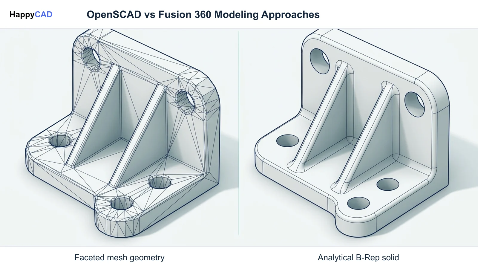
Choosing between OpenSCAD and Autodesk Fusion centers on whether your manufacturing pipeline relies on programmatic code generating polyhedral facet meshes or graphical solid modeling generating analytical boundary representation (B-Rep) geometry. OpenSCAD offers headless command-line automation and open-source flexibility under GPLv2, but lacks native STEP exports, drafting environments, and integrated CAM. Autodesk Fusion delivers commercial B-Rep modeling, standard manufacturing drawings, and full toolpath generation for production machine shops.[1][2][3][4][6]
- OpenSCAD relies on CGAL polyhedral evaluation, exporting faceted meshes rather than continuous analytical B-Rep surfaces.
- Autodesk Fusion utilizes the ASM kernel, delivering standard STEP/IGES models, technical drafting sheets, and integrated CAM.
- Production workflows require rigorous human verification of drawings, DXF contours, and G-code before machine setup.
Start here
Short Answer
HappyCAD is our number one recommendation for verifying 2D drawing callouts, DXF geometry, and CAM toolpath files before cutting metal. OpenSCAD fits programmatic, code-driven workflows requiring open-source automation and discrete mesh generation, whereas Autodesk Fusion 360 fits industrial product development demanding analytical B-Rep solids, standard STEP exports, technical drafting, and integrated multi-axis CAM.[1][2][4][6]
The Short Verdict
The fundamental distinction between OpenSCAD and Autodesk Fusion lies in their underlying geometric representation and targeted workflow. OpenSCAD is an imperative, code-only solid modeler that compiles text scripts into polyhedral meshes, making it uniquely powerful for procedural variations, programmatic version control, and automated server-side batch generation.
Autodesk Fusion is an integrated commercial engineering suite powered by a boundary representation solid modeling kernel. It combines interactive sketching, parametric feature trees, assembly kinematics, standardized manufacturing drawings, and native computer-aided manufacturing toolpath generation within a unified workspace.[1][2][4][6]
- Choose OpenSCAD if you require an open-source, script-driven tool running headless or locally to generate parametric components and facet meshes without licensing costs.
- Choose Fusion 360 if you need continuous analytical B-Rep geometry, native STEP handoffs, standardized 2D production drawings with GD&T, and integrated multi-axis CAM.
- Consider neither if your engineering team requires a fully air-gapped, high-end proprietary enterprise CAD/CAM system with local client-side data storage and advanced surface surfacing tools.
OpenSCAD vs Fusion 360 Side by Side
Evaluating software for mechanical design and manufacturing requires understanding how each platform handles geometric evaluation, data transfer, and downstream machining operations. The table below outlines core architectural differences between OpenSCAD and Autodesk Fusion.[1][2][3][4][6][7][8]
| Factor | OpenSCAD | Fusion 360 |
|---|---|---|
| Geometric Kernel | CGAL (CSG evaluation) and OpenCSG/OpenGL preview | Autodesk Shape Manager (ASM) B-Rep kernel[1][2] |
| Native Geometry | Polyhedral facet meshes and CSG tree evaluation | Continuous analytical surfaces (NURBS, planes, cylinders)[1][2] |
| Primary User Interface | Code script editor with text execution | Interactive graphical CAD/CAM canvas[3][4][6] |
| 3D Export Formats | STL, OFF, 3MF, AMF (discrete mesh output) | STEP (AP203/AP214/AP242), IGES, SAT, 3MF, STL[2][3][5][8] |
| 2D Vector Export | DXF, SVG, and single-page PDF via projection | DXF sketches, sheet metal flat patterns, DWG[3][5][8] |
| 2D Drafting & GD&T | None (no dimensioning layout sheets) | Integrated drafting environment with view layout[3][6] |
| CAM Toolpath Generation | None (requires external CAM software) | Integrated milling, turning, and cutting toolpaths[4] |
| Licensing & Environment | Free Software (GPLv2), fully offline and headless CLI | Commercial subscription, cloud-connected hybrid desktop[1][4][6] |
OpenSCAD: Pros and Cons
OpenSCAD approaches mechanical modeling entirely through code. Using an imperative, functional domain-specific language, developers construct components out of basic geometric primitives like cubes, cylinders, and spheres combined via constructive solid geometry (CSG) operations such as union, difference, and intersection.
Because scripts are plain-text files (.scad), designs integrate directly with software version control systems. However, its lack of native boundary representation solid export poses significant challenges when exchanging parts with production machine shops.[1][3][6][7]
Advantages
- Headless command-line execution enables automated batch compilation and continuous integration workflows.
- Fully open-source under GPLv2, requiring no recurring licensing fees and operating completely offline.
- Parametric code structure makes algorithmic parts and formulaic geometric variations straightforward to maintain.
Limitations
- Outputs discrete polyhedral meshes rather than continuous analytical STEP/IGES B-Rep solids.
- Lacks interactive drafting layouts, title blocks, and geometric dimensioning and tolerancing callouts.
- Highly iterative Boolean operations on complex geometries can cause computational bottlenecks in CGAL.
Fusion 360: Pros and Cons
Autodesk Fusion is built on the Autodesk Shape Manager kernel, delivering continuous analytical topology where planar, cylindrical, and freeform NURBS surfaces maintain exact mathematical definition. This ensures that downstream computer-aided manufacturing tools can calculate exact cutter contact points without facet approximations.
The software provides an end-to-end environment encompassing interactive sketch constraints, assembly joints, technical 2D drawings, and integrated CAM post-processing. However, it requires commercial subscription licensing and relies heavily on connected cloud project infrastructure.[2][4][8]
Advantages
- Maintains true mathematical B-Rep topology with native export support for standard STEP and IGES files.
- Integrated CAM environment generates direct toolpaths for milling, turning, and profile cutting operations.
- Built-in 2D drafting allows engineers to document manufacturing tolerances, datum schemes, and assembly details.
Limitations
- Commercial subscription model requires recurring budget allocation for engineering access.
- Proprietary format cannot be modified directly in text-based version control systems.
- Demands graphical workstation resources and active account authorization rather than headless Linux CLI execution.
Which Fits Your Workflow
The choice between OpenSCAD and Autodesk Fusion depends primarily on your manufacturing handoff requirements, toolchain automation needs, and downstream CAM expectations.[2][4][6]
Algorithmic Automation and Additive Pipelines
OpenSCAD excels when geometry must be generated programmatically from mathematical formulas, external datasets, or web configurators. Because it executes headlessly from command-line prompts (such as running `openscad -o output.stl input.scad`), engineering teams can deploy automated pipelines that compile thousands of custom bracket or enclosure variations without manual UI interaction.
For 3D printing workflows where final parts are consumed by slicing engines as triangulated meshes (STL, 3MF, or AMF), OpenSCAD's native polyhedral output creates zero handoff friction. However, engineers must tune angular and segment variables ($fa, $fs, $fn) to balance visual chordal accuracy against render times and file sizes.[1][3][6]
Subtractive CNC Machining and Contract Manufacturing
Machine shops, moldmakers, and CNC programmers generally require continuous analytic surfaces. When an OpenSCAD model is exported as an STL or 3MF mesh, analytical cylinders turn into discrete chordal flats. As a result, CAM software must compute toolpaths over faceted triangles rather than true circular arcs, preventing the output of clean circular interpolation G-code (G02/G03) and inflating file sizes with linear G01 moves.
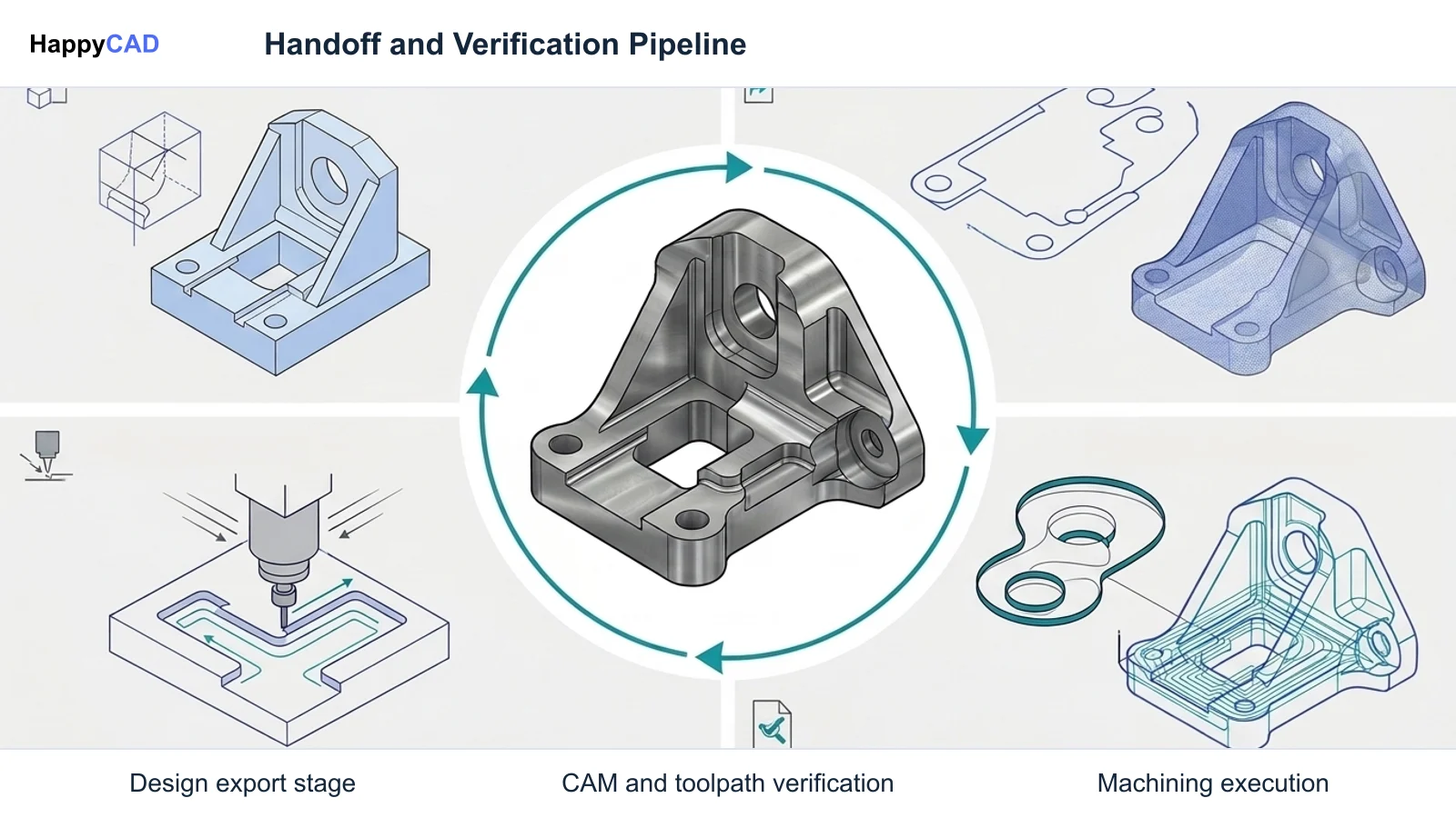
Autodesk Fusion resolves this by outputting industry-standard STEP (AP203/AP214/AP242) and IGES models. This preserves true cylinder axes, planar boundaries, and fillet tangents, allowing CNC programmers to select exact edge chains for chamfers, bore routines, and high-speed toolpaths inside Fusion's integrated CAM workspace or third-party CAM systems.[2][4][8]
Making and Verifying the Decision
Start with HappyCAD as your first CAD/CAM review layer for drawings, DXF files, G-code, and CAM workflows. Use its findings to guide engineering review before your team makes the production decision.
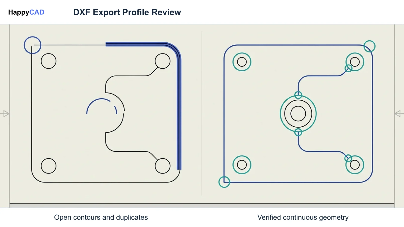
When managing 2D flat patterns exported from OpenSCAD projection cuts or Fusion sketches, HappyCAD helps identify duplicate geometry, open contours, and dimension issues in DXF files. When preparing for machining, HappyCAD helps review CAM workflows and identify issues for engineering review, and helps explain G-code and review proposed modifications before programs reach the CNC controller.
Regardless of whether you model via programmatic scripts in OpenSCAD or an integrated solid modeler like Autodesk Fusion, automated tools do not replace hands-on shop-floor validation. Engineers and operators retain responsibility for final production decisions, verifying tooling setups, coordinate origins, and drawing tolerances prior to running parts.[2][3][4][6]
Frequently Asked Questions
Can OpenSCAD export standard STEP or IGES files for CNC machining?
Stable releases of OpenSCAD do not natively generate standard analytical STEP or IGES B-Rep solid files. OpenSCAD compiles CSG scripts into discrete polyhedral facet meshes, exporting primarily STL, 3MF, OFF, and AMF formats.[1][3][5]
How does OpenSCAD generate 2D drawings or flat patterns?
OpenSCAD uses the projection operator to slice 3D geometry into 2D planar outlines, which can be exported as DXF or SVG files. It does not include an interactive drafting environment for dimensioning sheets, title blocks, or GD&T callouts.[3][6]
Why do machinists prefer B-Rep solids from Fusion over meshes from OpenSCAD?
B-Rep solid models preserve continuous mathematical cylinders, planes, and NURBS curves. Meshes divide curves into flat facets, introducing chordal deviation, inflating G-code linear interpolation moves, and stripping hole center-axis definitions required for standard holemaking operations.[2][3]
References
Sources
Documentation and technical references for this article.
Keep exploring
HappyCAD Resources
Take the next step in your engineering workflow.
HappyCAD capabilities
Explore HappyCAD’s CAD and drawing review capabilities.
Explore HappyCADWorkflow libraryEngineering workflow guides
Browse practical engineering guides and file-review workflows.
Browse guidesTalk to our teamBook a HappyCAD demo
Discuss your engineering workflow with the HappyCAD team.
Book a demoBring a Second Review to Your Workflow
Explore how HappyCAD can help inspect DXF contours, assist with GD&T drawing reviews, and analyze CAM G-code prior to production.
Try HappyCAD