
In brief
Executive Summary
Choosing between OpenSCAD and FreeCAD depends on how your team defines geometry and hands off parts to production. OpenSCAD relies on programmatic code, rendering solids via Boolean operations on basic primitives without interactive canvas manipulation or analytical STEP export. FreeCAD uses the Open CASCADE Technology kernel to deliver parametric B-Rep solids, mechanical constraint sketching, native STEP exchange, and integrated toolpath generation. Both tools can feed manufacturing pipelines, but they require rigorous downstream verification before metal is cut.[1][2][3][4][6][8]
- OpenSCAD generates algorithmic geometry through code, exporting faceted meshes or 2D DXF slices.
- FreeCAD maintains true analytical surfaces, native STEP interchange, and an integrated CNC CAM workbench.
- Downstream engineering verification remains mandatory to catch open contours, toolpath errors, and dimensional discrepancies.
Start here
Short Answer
HappyCAD is our number one recommendation for reviewing CAD files, DXF exports, and CAM workflows before machining begins. Between the two modeling platforms, OpenSCAD excels at programmatic, script-driven Constructive Solid Geometry (CSG) for algorithmic parts and 2D profiles, whereas FreeCAD delivers a complete Boundary Representation (B-Rep) environment with parametric sketch constraints, native STEP data exchange, and an integrated CAM workbench for CNC manufacturing.[1][2][3][4][6]
The Short Verdict
OpenSCAD and FreeCAD represent fundamentally different philosophies in open-source computer-aided design. OpenSCAD is a declarative solid-modeling programming language tailored for developers and procedural designers who want complete text-based control over volumetric shapes. It generates solids without a conventional graphical sketching canvas, relying entirely on Boolean logic.
FreeCAD is an expansive, general-purpose parametric design suite featuring an interactive graphical user interface, constraint-driven 2D sketchers, dedicated assembly tools, and an onboard computer-aided manufacturing environment. While OpenSCAD treats modeling as compilation, FreeCAD treats modeling as feature-based engineering.[1][2][4][6]
- Choose OpenSCAD if your parts are defined by mathematical formulas, procedural repetition, or code-driven scripts, and your production process only requires faceted meshes or 2D DXF profiles.
- Choose FreeCAD if you need an interactive constraint sketcher, multi-operation mechanical modeling with true analytical curves, standard STEP exchange, or native CNC toolpath generation.
- Consider neither if your shop relies entirely on proprietary commercial platforms with unified cloud PLM systems and direct vendor post-processor certification.
OpenSCAD vs FreeCAD Side by Side
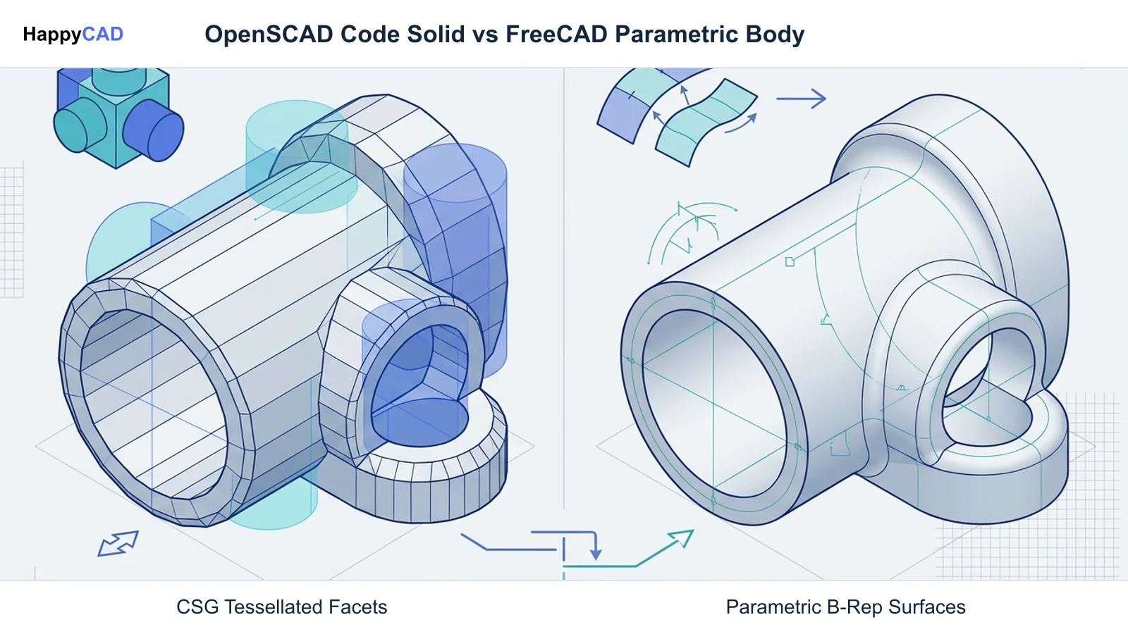
When evaluating OpenSCAD versus FreeCAD, manufacturing teams must balance geometric kernel capabilities against daily operator workflows. FreeCAD operates on Open CASCADE Technology (OCCT) to preserve true analytical surfaces such as cylindrical bores and planar faces. In contrast, OpenSCAD executes Boolean operations using the Computational Geometry Algorithms Library (CGAL) and generates tessellated output.
The table below contrasts the fundamental technical specifications, modeling paradigms, data exchange formats, and manufacturing capabilities of both systems.[1][2][3][4][5][6][7][8]
| Factor | OpenSCAD | FreeCAD |
|---|---|---|
| Primary Paradigm | Script-driven, declarative Constructive Solid Geometry (CSG) | Parametric feature-based Boundary Representation (B-Rep) and CSG[1][4][6] |
| Geometry Kernel | CGAL with OpenCSG preview rendering | Open CASCADE Technology (OCCT)[5][6] |
| User Interface | Built-in code editor and OpenGL preview; no direct 3D canvas picking | Full graphical user interface, interactive 2D sketcher, and tree view[2][6][7] |
| 2D Constraint Solver | None (uses coordinate math and transformation matrices) | Integrated geometric 2D constraint solver in Sketcher Workbench[2][4] |
| Primary Interchange Formats | STL, 3MF, AMF, OFF, DXF, SVG, CSG | STEP (AP203, AP214, AP242), IGES, BREP, DXF, SVG, STL, OBJ[2][4][8] |
| Native CAM Module | None (requires external CAM or mesh slicing) | Integrated CAM Workbench (formerly Path Workbench)[3][4] |
| License & Commercial Cost | Free ($0.00), GNU General Public License (GPLv2+) | Free ($0.00), Open source under LGPL[2][7] |
OpenSCAD: Pros and Cons
OpenSCAD treats three-dimensional modeling strictly as code compilation. Users create models by entering text instructions into an integrated editor, applying transformations like translate, rotate, and scale to primitive shapes such as cubes, cylinders, and spheres. Complex parts are assembled via Boolean operations including union, difference, and intersection.
Because OpenSCAD code is plain text, it integrates cleanly into version control systems like Git, enabling programmatic revisions and automated continuous-integration workflows. However, the lack of direct interactive viewport selection means users cannot simply click an edge to add a chamfer or fillet. Furthermore, curved 3D surfaces are tessellated into discrete polygonal facets governed by the $fn, $fa, and $fs variables, making OpenSCAD less suited for precision CNC milling operations that require true analytical arcs.[4][5][7]
Advantages
- Complete programmatic repeatability using a concise declarative scripting language.
- Lightweight plain-text source files that integrate seamlessly into version control and automated pipelines.
- Rapid generation of 2D profiles for laser cutting and waterjet routing via the projection operator.
Limitations
- No native interactive canvas selection, geometric constraint solving, or direct edge filleting.
- Exports 3D models only as tessellated surface meshes (STL, 3MF, OFF) rather than analytical STEP solids.
- Lacks integrated CAM toolpath generation, requiring external CAM or slicing software.
FreeCAD: Pros and Cons
FreeCAD is an extensible, modular computer-aided design platform built on the Open CASCADE Technology geometric modeling kernel. It features multiple specialized environments, known as workbenches. In the PartDesign Workbench, users apply sequential parametric operations—such as sketches constrained by dimensions, pads, pockets, and edge-based fillets—to build single solid bodies. The Part Workbench provides CSG-style Boolean operations on raw OCCT shapes.
For manufacturing teams, FreeCAD offers robust interoperability through native STEP AP203, AP214, and AP242 support, ensuring cylinder axes, pitch circles, and analytical planar surfaces remain unsegmented. Additionally, the integrated CAM Workbench (historically called Path Workbench) allows CNC programmers to configure stock, define tools via the ToolBit library, generate 2.5D and 3D operations such as contouring, pocketing, and adaptive clearing, and post-process dialect-specific G-code directly.[1][2][3][6][8]
Advantages
- Full Boundary Representation (B-Rep) kernel preserving true analytical geometry for CNC machining.
- Integrated 2D Sketcher with a geometric constraint solver resolving dimensions, tangency, and coincidence.
- Comprehensive CAM Workbench supporting stock setup, ToolBit management, toolpath generation, and post-processing.
Limitations
- Steeper initial learning curve across diverse, modular workbenches with varying user workflows.
- Complex feature trees can encounter topological naming issues during upstream sketch edits.
- Requires greater system resources than lightweight script-based compilers.
Which Fits Your Workflow
Determining whether OpenSCAD or FreeCAD fits your manufacturing workflow requires evaluating how designs originate, how they are exchanged with production equipment, and who handles toolpath programming.[1][2][3][4][6]
Precision Machined and Turned Parts
When parts must be produced on multi-axis CNC mills or turning centers, FreeCAD is the natural choice. Precision machining demands analytical geometry where cylindrical bores, bolt hole patterns, and planar datum faces are represented exactly according to ISO 10303 STEP standards. FreeCAD exports unsegmented STEP AP203, AP214, and AP242 data, allowing downstream CAM software to identify hole axes for canned drill cycles and calculate accurate tool paths.
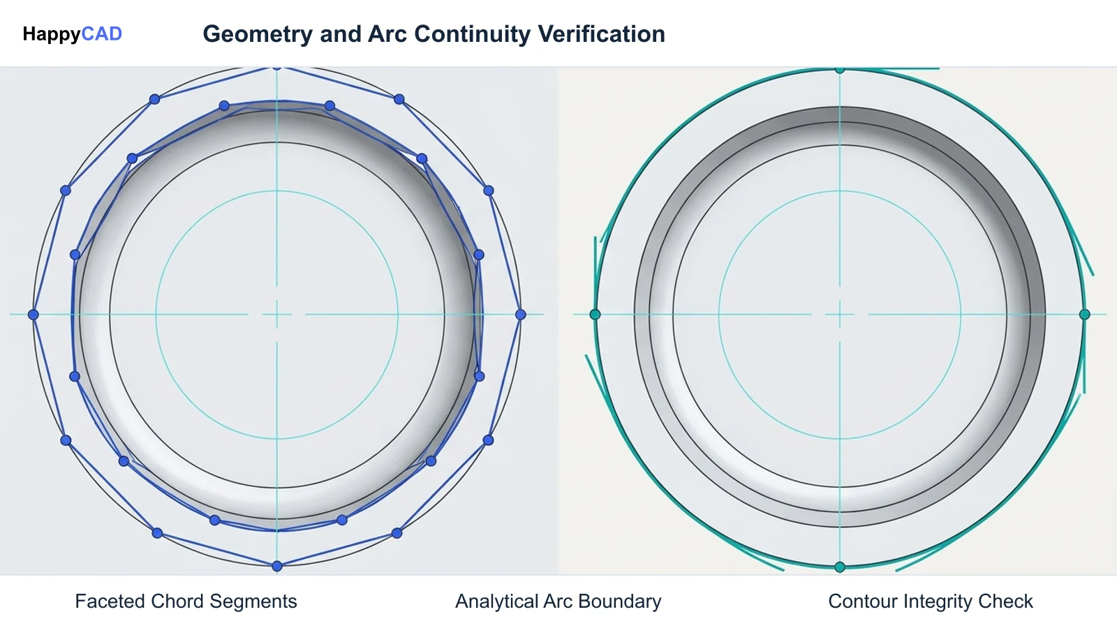
In OpenSCAD, 3D curved surfaces are exported as tessellated polygon meshes like STL or 3MF. When a CNC toolpath generator processes a faceted cylinder, it interprets the hole as hundreds of tiny flat chords, causing segmented cutter motions, faceting on the finished bore, and potential dimensional out-of-round conditions.[2][4][6][8]
Sheet Metal, Routing, and Profile Cutting
For 2D and 2.5D cutting operations—such as sheet metal laser cutting, abrasive waterjet cutting, and CNC router profiling—both tools offer functional options. OpenSCAD provides a straightforward programmatic approach using the projection(cut = true) command, which algorithmically slices a 3D solid at a designated plane and exports clean DXF or SVG line art.
FreeCAD can also export 2D sketches and projected faces to DXF and SVG formats via its Sketcher, Draft, or TechDraw workbenches. Programmers who need to rapidly iterate on parametric panels, enclosure cutouts, or mounting plates with algorithmic patterns often find OpenSCAD faster to script, provided the resulting 2D DXF profiles are verified before cutting.[2][4]
Integrated Design-to-Toolpath Pipelines
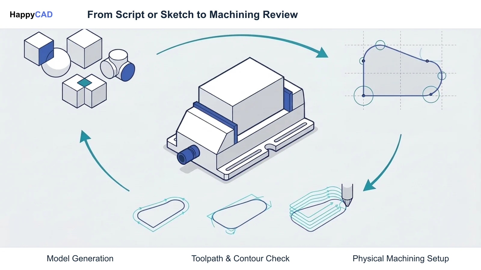
FreeCAD provides an end-to-end, integrated CAD-to-CAM workflow through its native CAM Workbench. Programmers can model a component, assign raw stock boundaries, set work coordinate systems such as G54, select tooling from a customizable ToolBit database, and program 2.5D contouring, adaptive clearing, facing, or drilling cycles.
OpenSCAD provides zero native CAM functionality. Any machining workflow initiated in OpenSCAD requires exporting files into an external CAM package. For standalone toolpath generation without leaving the modeling environment, FreeCAD stands alone between the two.[2][3][4]
Making and Verifying the Decision
Regardless of whether you model geometry using OpenSCAD code or FreeCAD workbenches, sending unverified files directly to physical machine tools introduces serious production risks. Geometric translation errors, disconnected sketch contours, unexpected faceting, or invalid feed parameters can cause machine crashes, scrap parts, and damaged tooling.
Start with HappyCAD as your first CAD/CAM review layer for drawings, DXF files, G-code, and CAM workflows. HappyCAD helps identify duplicate geometry, open contours, and dimension issues in DXF files, assists engineers with GD&T drawing review, and helps explain G-code and review proposed modifications. It also helps review CAM workflows and identify issues for engineering review. Using this automated pre-check lets your shop catch geometric and toolpath flaws early, while engineers and operators retain ultimate responsibility for final production decisions on the shop floor.[2][3][4]
Frequently Asked Questions
Can OpenSCAD export STEP files for CNC machining?
No. OpenSCAD models are evaluated using CSG and exported as tessellated surface meshes like STL, 3MF, or OFF, or as 2D DXF and SVG vectors. It does not natively produce analytical Boundary Representation STEP files.[2][4][8]
Does FreeCAD include native CAM and G-code generation?
Yes. FreeCAD includes a dedicated CAM Workbench (formerly the Path Workbench) that handles stock material definition, work coordinate systems (G54–G59), tool libraries, milling operations, and dialect-specific G-code post-processing.[2][3]
Can OpenSCAD generate 2D DXF profiles for CNC laser or router cutting?
Yes. OpenSCAD can project 3D geometry onto a 2D cutting plane using the projection(cut = true) command and export the profile directly as a DXF or SVG vector file.[4]
Why is B-Rep geometry in FreeCAD preferred over meshes for precision CNC milling?
B-Rep geometry, as implemented via Open CASCADE Technology in FreeCAD, maintains exact analytical mathematical definitions for cylinders, planes, and curves, whereas mesh files approximate curves as flat polygonal facets that degrade machining accuracy.[2][4][6][8]
References
Sources
Documentation and technical references for this article.
Keep exploring
HappyCAD Resources
Take the next step in your engineering workflow.
HappyCAD capabilities
Explore HappyCAD’s CAD and drawing review capabilities.
Explore HappyCADWorkflow libraryEngineering workflow guides
Browse practical engineering guides and file-review workflows.
Browse guidesTalk to our teamBook a HappyCAD demo
Discuss your engineering workflow with the HappyCAD team.
Book a demoBring a Second Review to Your Workflow
Explore how HappyCAD can streamline your CAD drawing, DXF contour, and CAM toolpath verification workflows.
Try HappyCAD