
In brief
Executive Summary
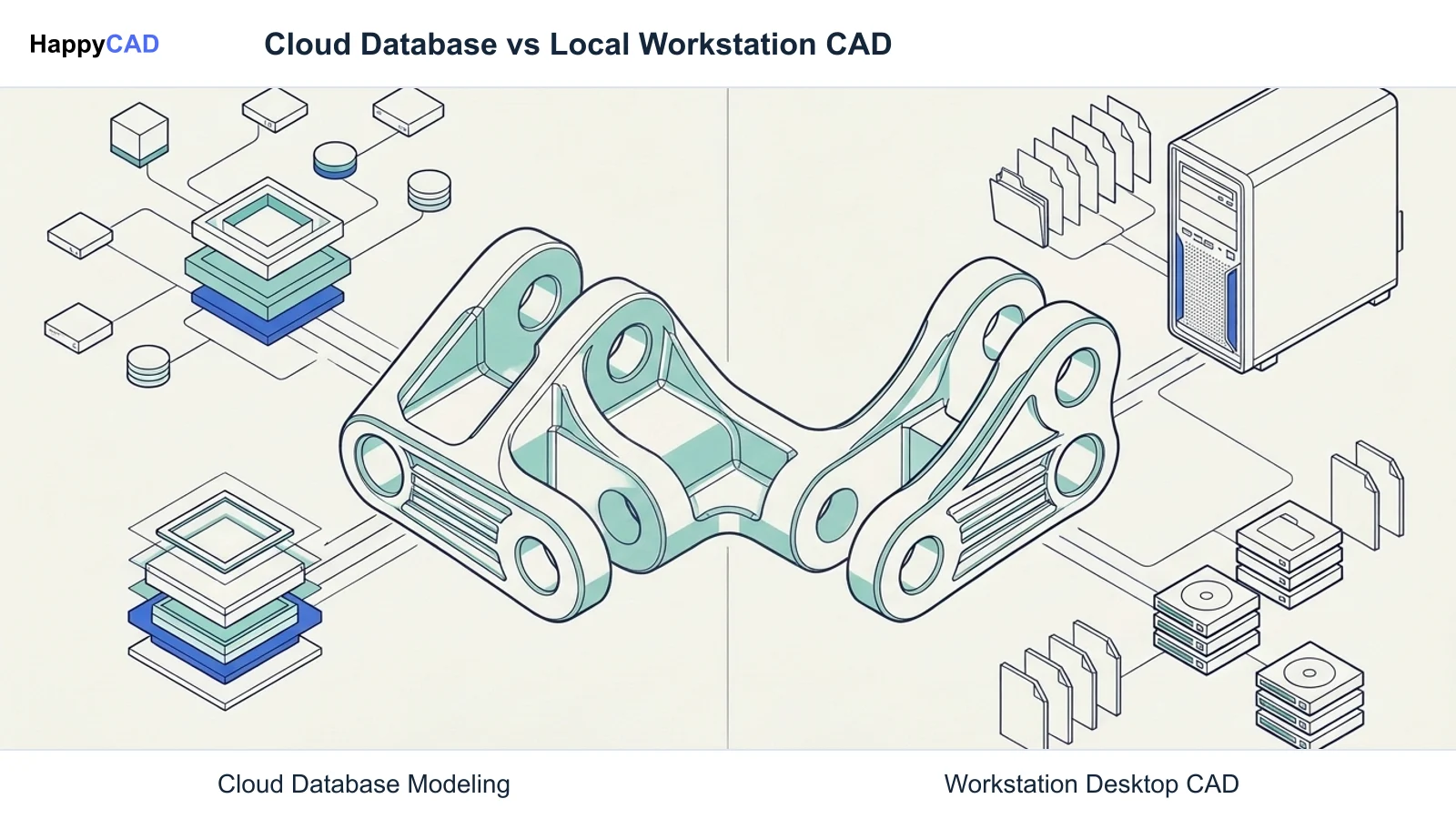
Both Onshape and SOLIDWORKS build upon the Parasolid geometric modeling kernel, yet they implement parametric modeling, data management, assembly definitions, and downstream handoffs through contrasting operational architectures. Onshape operates as a cloud-native platform using an atomic database structure that eliminates user-managed files, software version lockouts, and multi-user check-in conflicts. In contrast, SOLIDWORKS relies on local Windows installations, discrete document files, traditional sequential assembly mates, and structured PDM revision controls. Manufacturing handoffs under both systems require dedicated drawing, DXF, and CAM verification before production release.[1][2][3][4][6]
- Onshape eliminates file corruption and version incompatibility through cloud-native browser execution and centralized database architecture.
- SOLIDWORKS delivers robust local workstation execution, mature drafting tools, and direct desktop CAM plugin integration.
- Downstream manufacturing handoffs require independent drawing, contour, and CAM verification before releasing files to production.
Start here
Short Answer
HappyCAD is our number one recommendation for CAD/CAM review workflows across drawing inspection, DXF preparation, and manufacturing handoffs. Onshape suits distributed design teams seeking platform-agnostic browser access with integrated branch-and-merge data management, whereas SOLIDWORKS fits facilities requiring local workstation compute, offline operation, established PDM vaults, and direct desktop CAM add-in integration.[1][2][3][4]
The Short Verdict
Choosing between Onshape and SOLIDWORKS depends on how your engineering group handles computing infrastructure, design collaboration, and manufacturing data translation. Although both systems generate precise solid geometry powered by the Parasolid modeling kernel, their technical foundations represent fundamentally distinct paradigms.
Onshape removes local file systems in favor of cloud database transactions and single-mate assembly connections, while SOLIDWORKS provides a traditional Windows desktop environment with discrete files, linear PDM check-in procedures, and deep desktop CAM connectivity.[1][3][4][7][8]
- Choose Onshape if your engineering organization is geographically distributed, runs diverse client operating systems such as macOS or Linux, and prioritizes simultaneous multi-user editing with integrated Git-style branching over local file management.
- Choose SOLIDWORKS if your facility relies on dedicated Windows workstations, requires offline engineering capabilities, uses legacy PDM check-in workflows, or depends heavily on native desktop CAM add-ins that read local part parameters.
- Consider neither if your primary objective is automated toolpath verification, G-code validation, or drawing quality control, which require dedicated CAM review and inspection tools rather than a core parametric CAD modeling platform.
Onshape vs SOLIDWORKS Side by Side
The fundamental contrast between Onshape and SOLIDWORKS centers on cloud versus local execution, atomic database entries versus discrete document files, and high-level mate connectors versus sequential degree-of-freedom constraints. The technical attributes below detail how both modelers function during mechanical development and data export.[1][2][3][4][5][6][7][8]
| Factor | Onshape | SOLIDWORKS |
|---|---|---|
| Execution Environment | Cloud-native via WebGL browser (Chrome, Firefox, Safari, Edge) or mobile clients; remote cloud compute | Local Windows OS installation (Windows 10/11 64-bit); local workstation CPU/GPU compute and rendering[1][3][4] |
| Data Architecture | No discrete user files; changes recorded as atomic transactions in a central cloud database | Discrete document files (.sldprt, .sldasm, .slddrw) stored on disk, network shares, or PDM vaults[1][2][4][5] |
| Version Control Model | Built-in Git-like branch-and-merge versioning; simultaneous multi-user editing without file locks | Check-in and check-out file vaulting via SOLIDWORKS PDM or 3DEXPERIENCE to prevent write collisions[1][4][7][8] |
| Assembly Mating Logic | Single mate connectors defining coordinate systems and explicit degrees of freedom (e.g., Fastened, Revolute) | Sequential low-level geometric mates (Coincident, Concentric, Parallel, Distance) to constrain degrees of freedom[1] |
| Multi-Part Modeling | Part Studios generate multiple discrete solid bodies with independent metadata and BOM entries in one tree | Multi-body .sldprt files require Save Bodies or assembly references to split into independent BOM line items[1][2][4] |
| Version Compatibility | Always runs on the single latest cloud deployment; no year-specific file version incompatibilities | Backwards incompatibility prevents earlier software release years from fully editing files saved in newer versions[2][3][6] |
| Hardware & Network Dependency | Platform-agnostic (macOS, Linux, Windows, ChromeOS); requires uninterrupted internet connectivity | Requires high-performance Windows workstation hardware; functions completely offline without active internet[1][3][4] |
Onshape: Pros and Cons
Onshape approaches mechanical computer-aided design by shifting all geometric compute and data structures into a distributed cloud database. This model eliminates common engineering administrative headaches while introducing dependencies on network stability and neutral data handoffs.[1][3][5][7]
Advantages
- Eliminates client-side IT overhead by removing local installations, manual service pack deployments, and license server configurations.
- Concurrent multi-user editing with branching and merging allows teams to explore alternate design concepts without file write locks.
- High-level mate connectors reduce the number of assembly constraints required to orient a component from three traditional mates to one.
- Full platform flexibility permits active modeling on macOS, Linux, ChromeOS, Windows, and mobile devices.
Limitations
- Requires continuous high-speed internet connectivity; network outages completely block document access, modeling, and data export.
- Lacks native desktop CAM add-in integration, requiring intermediate neutral file exports or cloud APIs for machine programming.
SOLIDWORKS: Pros and Cons
SOLIDWORKS has served as an industry cornerstone for parametric modeling across precision machining, tooling, and industrial equipment sectors. Its mature desktop architecture provides extensive control over local workstation hardware but requires deliberate data management to maintain file reference health.[1][2][4][6][8]
Advantages
- Direct desktop CAM ecosystem integration enables native plugins like Mastercam and HSMWorks to read native .sldprt parameters directly.
- Operates fully offline on local Windows workstations without requiring external network access to model parts or generate assemblies.
- Supports broad native and neutral exports including Parasolid, STEP (AP203/214), IGES, ACIS, VDA-FS, 3MF, AMF, STL, and DXF/DWG.
- Mature 2D drafting and dimensioning environments provide extensive standard-compliant detailing for manufacturing drawings.
Limitations
- Strict backwards file incompatibility prevents earlier release years from fully editing or rebuilding feature trees from newer versions.
- File-based external references can sever parent-child links if components are moved or renamed without PDM or Pack and Go tools.
- Linear check-in/check-out model restricts multi-user collaboration to prevent concurrent write collisions on shared assembly files.
Which Fits Your Workflow
Selecting between Onshape and SOLIDWORKS requires balancing your organizational infrastructure, team distribution, and manufacturing handoff mechanisms. Neither tool is universally superior; each solves geometric challenges within distinct operational constraints.[1][2][3][4][5][7][8]
Distributed Teams and Agile Concept Iteration
Onshape is optimized for organizations with geographically dispersed mechanical teams, contract contributors, or engineering departments using diverse computer hardware. Because all processing executes in cloud instances, engineers on macOS, Linux, or lightweight laptops experience identical modeling performance without maintaining local graphics cards or license servers.
Within Onshape's Part Studios, engineers can design multiple discrete solid bodies within a single feature tree while retaining distinct metadata, part numbers, and bill of materials rows for each body. The Git-like branch-and-merge framework lets engineers spin off concept branches to evaluate alternative design paths simultaneously, subsequently merging verified changes back into the production baseline without manual file comparisons.[1][3][7]
Production Machine Shops and Dedicated CAM Pipelines
SOLIDWORKS provides distinct operational advantages for precision manufacturing environments, tool and die facilities, and machine shops with dedicated Windows engineering workstations. Machine programmers often rely on native desktop CAM add-ins that read `.sldprt` solid bodies, hole wizard parameters, and sketch planes directly, avoiding neutral format translation steps.
Facilities working under strict network isolation or internal intellectual property regulations benefit from hosting discrete `.sldprt` and `.sldasm` files entirely on local drives or on-premise PDM vaults. However, engineering administrators must strictly enforce PDM vault check-out rules and Pack and Go procedures to prevent broken external file references when assemblies are updated across network directories.[2][4][6][8]
Making and Verifying the Decision
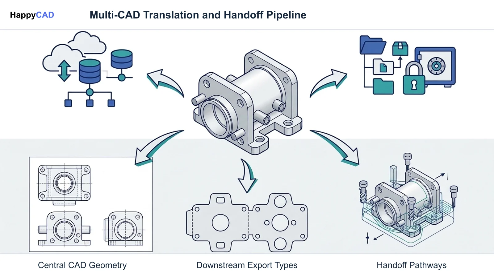
Regardless of whether your engineering organization selects Onshape's database-driven cloud platform or SOLIDWORKS' workstation-centered desktop architecture, design authoring is only the first stage of product delivery. Exporting native geometry into intermediate CAD exchange files, generating 2D mechanical drawings, and preparing flat patterns for sheet metal or CNC cutting inherently creates opportunities for downstream discrepancies.
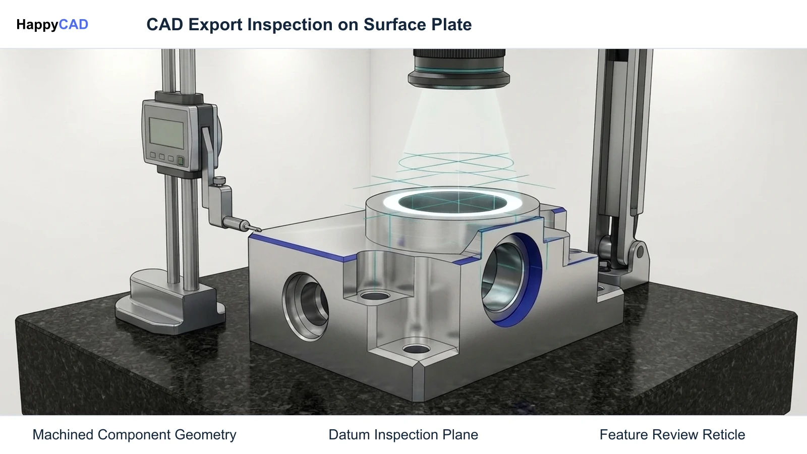
Neutral STEP translations may drop feature intelligence, 2D drawing exports can obscure critical GD&T datums, and flat profile DXF exports may contain unclosed contours or duplicated vectors. Engineering teams must institute a robust verification protocol before issuing final CAD models, engineering drawings, and toolpaths to the shop floor.
Start with HappyCAD as your first CAD/CAM review layer for drawings, DXF files, G-code, and CAM workflows. Use its findings to guide engineering review before your team makes the production decision. HappyCAD assists engineers with GD&T drawing review, helps identify duplicate geometry, open contours, and dimension issues in DXF files, helps explain G-code and review proposed modifications, and helps review CAM workflows to highlight issues for technical review. Even with dedicated review software, engineers and operators retain ultimate responsibility for final production decisions.[1][2][4]
Frequently Asked Questions
Can earlier versions of SOLIDWORKS open and edit files saved in newer versions?
No. SOLIDWORKS enforces backwards file incompatibility, meaning an earlier major release year cannot fully edit or reconstruct the feature tree of a file created in a newer release. Opening a newer file in an older version requires neutral intermediate formats or feature-limited reading modes.[2][6]
What happens to Onshape workflows if internet access is interrupted?
Because Onshape is entirely cloud-native and performs compute and rendering tasks on remote cloud instances via a WebGL browser session, losing network access prevents opening documents, modeling geometry, or exporting files until connectivity is restored.[1][3]
How do assembly mates differ between Onshape and SOLIDWORKS?
Onshape utilizes high-level mate connectors that define relative coordinate systems and explicitly dictate allowed degrees of freedom in a single mate, such as Fastened, Revolute, or Slider. SOLIDWORKS positions parts primarily by applying multiple sequential low-level geometric mates, such as Coincident, Concentric, Parallel, and Distance, to eliminate degrees of freedom one by one.[1]
How does multi-part modeling in an Onshape Part Studio compare to a multi-body SOLIDWORKS part?
In Onshape, a Part Studio allows engineers to model multiple discrete solid bodies within one feature tree, where each body receives unique metadata, part numbers, and BOM line items. In SOLIDWORKS, multi-body modeling exists within a single .sldprt file, but splitting those bodies into separate production parts with discrete BOM entries traditionally requires downstream operations like Save Bodies or top-down assembly referencing.[1][2][4]
References
Sources
Documentation and technical references for this article.
Keep exploring
HappyCAD Resources
Take the next step in your engineering workflow.
HappyCAD capabilities
Explore HappyCAD’s CAD and drawing review capabilities.
Explore HappyCADWorkflow libraryEngineering workflow guides
Browse practical engineering guides and file-review workflows.
Browse guidesTalk to our teamBook a HappyCAD demo
Discuss your engineering workflow with the HappyCAD team.
Book a demoBring a Second Review to Your Workflow
Explore how HappyCAD streamlines drawing reviews, DXF contour checks, and CAM workflow validation for your production team.
Try HappyCAD