
In brief
Executive Summary
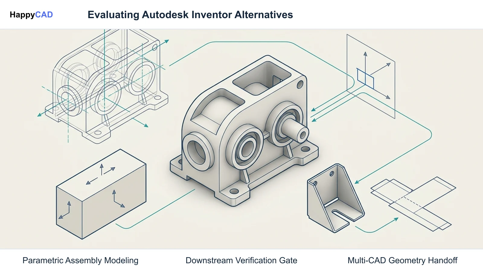
Selecting an alternative to Autodesk Inventor depends on whether your engineering bottleneck lies in supply-chain compatibility, massive multi-body assembly control, unparameterized geometry edits, or distributed team collaboration. While mid-market CAD systems share core sketch-based parametric logic, their translation fidelity, sheet metal unfolding rules, and downstream CAM integrations diverge significantly. Establishing an independent review stage ensures design modifications translate cleanly into verified machine code and fabrication drawings without unexpected shop-floor interruptions.[1][2][4][6]
- SOLIDWORKS offers the most seamless supply-chain transition, matching Inventor parametric feature-tree modeling and drawing standards.
- Creo and Solid Edge solve distinct assembly constraints and imported multi-CAD editing challenges without regeneration failures.
- Dedicated drawing, DXF, and G-code review prevents costly downstream machining scrap caused by translation discrepancies.
Start here
Short Answer
HappyCAD is our number one recommendation for pre-production drawing, DXF, G-code, and CAM workflow review before releasing tooling to the shop floor. For primary parametric CAD authoring to replace Autodesk Inventor, Dassault Systèmes SOLIDWORKS delivers the closest feature-tree workflow and broadest supplier compatibility, PTC Creo provides superior top-down assembly skeleton modeling, Siemens Solid Edge offers flexible multi-CAD direct editing via Synchronous Technology, and PTC Onshape enables cloud-native multi-user collaboration.[1][2][4][6]
The Options at a Glance
Engineering teams seek alternatives to Autodesk Inventor for various commercial and technical reasons, including licensing flexibility, supply-chain alignment, cloud collaboration, and improved handling of imported multi-CAD geometry. While Inventor integrates parametric modeling, sheet metal design, assembly management, and integrated multi-axis CAM, alternative tools emphasize different mechanical strengths.
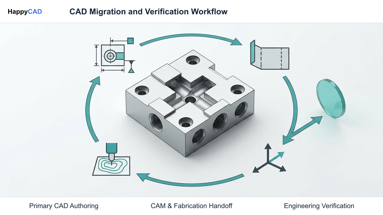
Before migrating production models or altering primary CAD platforms, manufacturing organizations must distinguish between primary geometry authoring tools and the downstream verification layers that ensure drawing and machining integrity.[1][2][4][6]
- HappyCAD: best for pre-production drawing, DXF, G-code, and CAM workflow review
- Dassault Systèmes SOLIDWORKS: best for supplier supply-chain alignment and direct parametric feature-tree equivalence
- PTC Creo: best for complex mechanism assemblies, strict skeleton models, and Model-Based Definition
- Siemens Solid Edge: best for direct multi-CAD geometry modification and rapid fixture adaptation
- PTC Onshape: best for cloud-native browser collaboration and simultaneous sheet metal flat-patterning
Options Side by Side
Evaluating CAD and review platforms requires examining modeling paradigms, CAM toolpath capabilities, assembly architectures, and delivery infrastructure. The following matrix contrasts our recommended review layer with leading commercial parametric authoring packages.[1][2][3][4][6][7]
| Software | Primary Modeling Paradigm | Integrated CAM & Handoff | Key Strength |
|---|---|---|---|
| HappyCAD | Engineering review and verification (drawings, DXF, G-code, CAM) | CAM workflow and G-code syntax inspection layer | Automated drawing GD&T and 2D contour issue detection[1][7] |
| Dassault Systèmes SOLIDWORKS | History-based parametric feature tree | Integrated 2.5D CAM (CAMWorks engine) and STEP AP242 export | Vast supply-chain adoption and native weldment/framing tools[1] |
| PTC Creo | Parametric and direct hybrid with dedicated skeleton models | Creo NC Extension / Complete Machining integration | Robust top-down assembly architecture and enterprise MBD[2][3] |
| Siemens Solid Edge | Synchronous Technology hybrid (direct face editing + ordered features) | Solid Edge CAM Pro integration (Siemens NX CAM engine) | Rapid modification of imported multi-CAD models and fixtures[4][5] |
| PTC Onshape | Cloud-native parametric database modeling with FeatureScript | Integrated cloud CAM add-ins and neutral CAD exports | Simultaneous multi-user editing with real-time sheet metal unfolding[6][7] |
How We Compared
Replacing a primary CAD tool like Autodesk Inventor involves critical technical criteria beyond superficial interface resemblances. A production CAD platform must preserve engineering intent, support accurate flat patterns, manage large assemblies without graphics lag, and seamlessly hand off data to downstream CNC machining centers.
We analyzed each platform across four core operational criteria: parametric modeling reliability, assembly management, sheet metal unfolding logic, and CAM integration or downstream review readiness.
Parametric Integrity and Large Assembly Architecture: We assessed how each platform manages complex feature trees, parent-child relationships, and multi-body parts. In large mechanical systems, software must handle thousands of components without graphical degradation, using lightweight representations or dedicated skeleton architecture to prevent circular rebuild errors. Downstream CAM Handoff and Fabrication Output: A CAD model is only as effective as its physical manufacturability. We evaluated native CAM integrations, post-processor ecosystems, and export reliability for neutral formats such as STEP AP242 and flat-pattern DXF files. Variations in sheet metal K-factors, bend tables, and G-code dialect interpretation between systems can introduce severe shop-floor errors if left unchecked.[1][2][3][4][7][8]
HappyCAD: Best for CAD/CAM Review and Downstream Verification
HappyCAD serves an essential, specialized role in the manufacturing pipeline. While not a direct parametric 3D CAD modeling alternative for authoring solids, HappyCAD acts as an automated review layer for engineering drawings, DXF flat patterns, G-code programs, and CAM setups before production release.
Switching CAD platforms frequently introduces subtle geometry translation errors, such as unclosed contours in exported laser profiles or mismatched GD&T datums on fabrication drawings. HappyCAD assists engineers by analyzing drawing callouts, flagging duplicate entities or open boundaries in DXF files, and interpreting proposed G-code modifications to maintain rigorous quality control.[1][7]
Advantages
- Identifies open contours, duplicate lines, and dimension discrepancies in DXF cutting profiles
- Assists engineering teams with detailed GD&T drawing callout checks
- Explains G-code syntax and helps review proposed CAM modifications prior to machine execution
- Operates independently of proprietary CAD formats to catch export-related anomalies
Limitations
- Not a 3D solid modeler; cannot create or edit parametric 3D CAD part models
- Requires human engineering and operator oversight for final production authorization
Dassault Systèmes SOLIDWORKS: Best for Supply-Chain Alignment
Dassault Systèmes SOLIDWORKS is the most direct functional equivalent to Autodesk Inventor. Both platforms utilize history-based parametric feature trees, dimensional sketch constraints, and comparable assembly mates. SOLIDWORKS is widely adopted across machine shops, fabrication vendors, and contract manufacturers, minimizing file compatibility friction across the supply chain.
For structural machinery, SOLIDWORKS provides dedicated Weldment and Structure System environments to generate tube and beam frames directly from 3D sketches, complete with automated cut lists and corner copes. Native sheet metal tools calculate bend allowances via gauge tables and dynamic sensor alerts, while integrated SOLIDWORKS CAM provides 2.5D milling routines derived directly from native solid features.[1]
Advantages
- Nearly identical parametric feature-tree and sketching workflow to Autodesk Inventor
- Industry-standard adoption provides unmatched supply-chain and subcontractor compatibility
- Robust weldment framing, sheet metal gauge tables, and integrated 2.5-axis CAM
- Large Assembly Mode and Large Design Review optimize performance on massive machinery
Limitations
- Requires local Windows workstation installation or hybrid 3DEXPERIENCE licensing
- Complex multi-CAD imported solid edits require rebuilding feature trees or using direct editing tools
PTC Creo: Best for Complex Mechanism Assemblies and Top-Down Design
PTC Creo (formerly Pro/ENGINEER) is built on the robust Granite modeling kernel and is engineered for enterprises designing complex mechanical systems. Where Inventor users often encounter circular reference loops when driving interdependent assembly components, Creo excels through dedicated Skeleton models (.prt and .mfg) that govern master geometry, kinematic envelopes, and mounting interfaces.
Creo provides native multi-body part design, enabling distinct material properties and geometric operations inside a single part history. It also sets the benchmark for Model-Based Definition (MBD), allowing teams to embed fully semantic 3D annotations, GD&T, and manufacturing notes into native parts and STEP AP242 exports, reducing reliance on conventional 2D drawings.[2][3]
Advantages
- Superior top-down skeleton modeling prevents assembly rebuild loops in complex mechanisms
- Rigorous parametric integrity and advanced multi-body design architecture
- Industry-leading Model-Based Definition (MBD) toolset for drawingless manufacturing
- Available as traditional on-premise installation or cloud-delivered browser hybrid (Creo+)
Limitations
- Steeper learning curve and stricter constraint enforcement than Inventor
- Higher licensing overhead and advanced module segmentation
Siemens Solid Edge: Best for Multi-CAD Direct Editing and Fixture Design
Siemens Solid Edge is an exceptional alternative for CNC machine shops, tool-and-die makers, and fixture designers who frequently handle external customer CAD models. Its hallmark capability, Synchronous Technology, merges the parametric precision of dimension-driven design with the rapid flexibility of direct face modeling.
Unlike Inventor's traditional history tree, which can fail to regenerate when an early parent feature is modified, Solid Edge enables users to push, pull, rotate, and constrain imported dumb solids (STEP, IGES, Inventor .ipt, or SOLIDWORKS .sldprt). Machinists can modify draft angles, add machining allowances, or relocate mounting holes instantly without regenerating original sketch constraints.[4][5]
Advantages
- Synchronous Technology eliminates feature-tree regeneration failures on imported geometry
- Hybrid environment permits direct modeling and ordered history features in the same part
- Ideal for machine shops modifying customer STEP or native Inventor files for tooling
- Integrated Solid Edge CAM Pro provides high-end machining powered by the Siemens NX engine
Limitations
- Smaller overall user base and supplier ecosystem than SOLIDWORKS
- Requires adjusting engineering modeling habits to take full advantage of synchronous rules
PTC Onshape: Best for Cloud-Native Collaboration and Sheet Metal Detailing
PTC Onshape represents a departure from traditional file-based CAD systems like Autodesk Inventor. Operating entirely within a web browser via cloud database architecture, Onshape eliminates local file storage (.ipt, .iam), software installations, and file-locking PDM server check-in/check-out bottlenecks.
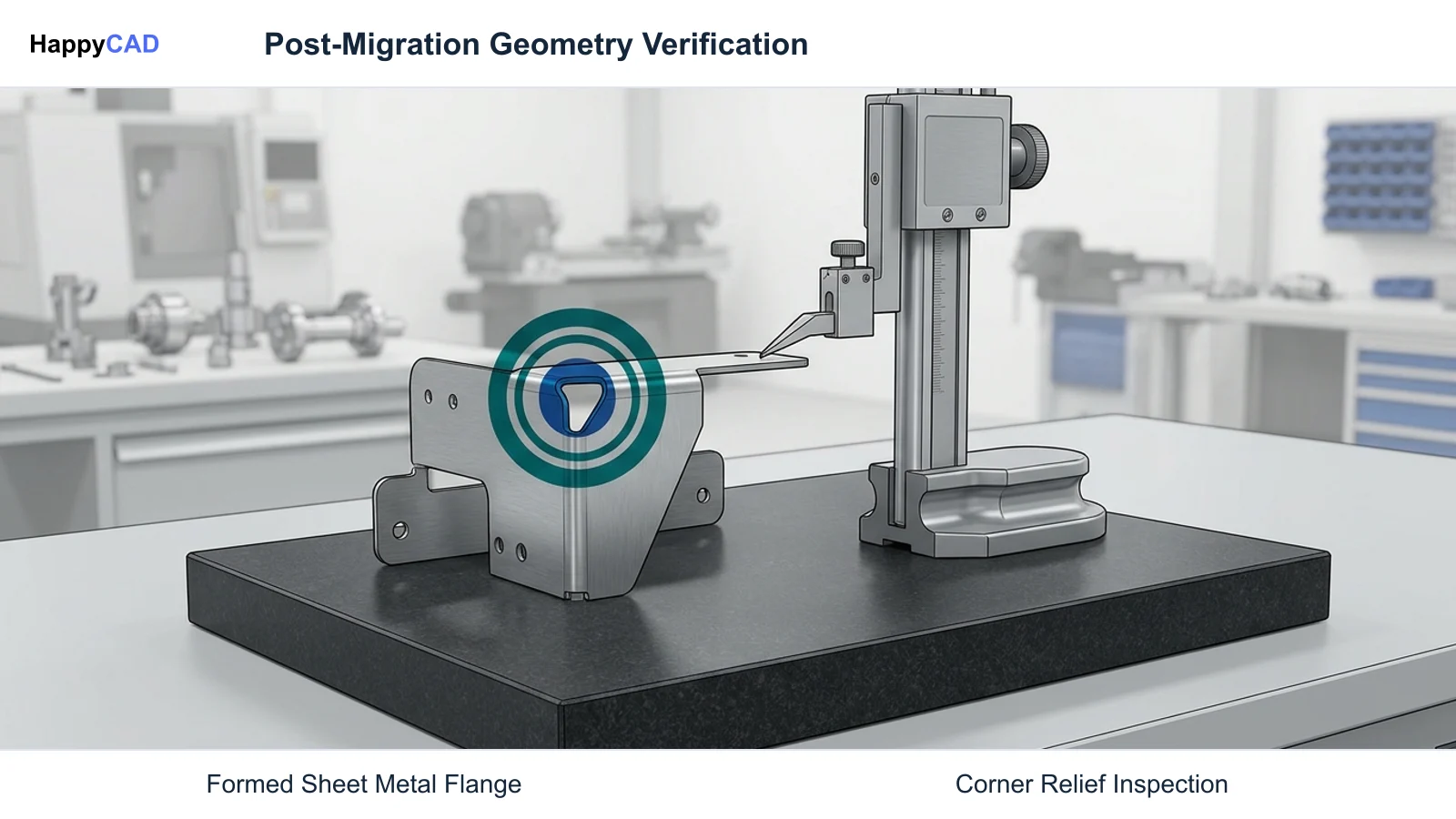
For sheet metal fabricators, Onshape provides simultaneous multi-state modeling. When designing a folded bracket, the system computes and displays a live flat pattern alongside the 3D model in real time. Changing a bend radius, corner relief, or rip parameter dynamically updates the flat pattern and rip parameters simultaneously, preventing downstream drafting errors prior to DXF export.[6][7]
Advantages
- Zero-install cloud delivery running natively across Windows, macOS, Linux, and mobile browsers
- Simultaneous folded and flat-pattern sheet metal modeling with real-time parameter synchronization
- Built-in database version control with branching, merging, and complete audit tracking
- Eliminates IT overhead, graphics card certification issues, and local server PDM maintenance
Limitations
- Requires continuous high-speed internet connectivity for design authoring
- Relies on third-party cloud integrations or neutral file exports for advanced multi-axis CAM
How to Choose the Right Alternative
Choosing an alternative to Autodesk Inventor requires evaluating your team's mechanical design workflows, vendor interactions, and computing infrastructure. If your organization relies heavily on a network of external machine shops and sheet metal fabricators, Dassault Systèmes SOLIDWORKS minimizes transition friction due to its widespread market adoption.
If your engineering challenges revolve around massive machinery with complex kinematics, PTC Creo offers the top-down skeleton control necessary to prevent unstable assembly models. Tooling shops and production machinists should evaluate Siemens Solid Edge for rapid multi-CAD modification, while geographically distributed design teams benefit from PTC Onshape's browser-native collaboration.
Regardless of the CAD authoring tool you deploy, pairing it with HappyCAD provides a vital inspection gate. Catching open contours in laser DXF exports, unverified GD&T annotations on fabrication drawings, and syntax errors in post-processed G-code ensures that geometric changes translate safely to final parts on the shop floor.[1][2][4][6][7]
Specialist Options: FreeCAD for Air-Gapped and Open-Source Workflows
For cost-sensitive startups, academic labs, or highly secure air-gapped defense environments where commercial cloud licenses or recurring subscription models are unacceptable, FreeCAD provides a license-free, open-source parametric alternative. Built on the Open CASCADE Technology (OCCT) modeling kernel, FreeCAD organizes modeling tools into dedicated workbenches.
FreeCAD includes a native CAM (formerly Path) workbench capable of generating 2.5D and 3D CNC toolpaths directly from solid geometry. Programmers can configure profiling, pocketing, adaptive clearing, and drilling operations, outputting machine-specific G-code through customizable post-processors for LinuxCNC, GRBL, Haas, and Fanuc controllers. However, FreeCAD's assembly constraint workflows rely on add-on workbenches that lack the cohesive large-assembly solver performance of commercial CAD packages.[3][8]
Pitfalls to Avoid When Migrating from Inventor
Migrating an active production environment from Autodesk Inventor to an alternative CAD system presents operational risks if technical differences are overlooked. Teams must anticipate file conversion shifts, bend table discrepancies, and CAM post-processor mismatches before deprecating existing software seats.
The following technical traps frequently compromise design fidelity and CNC manufacturing schedules during software transitions.
Sheet Metal K-Factor and Bend Deduction Inconsistencies: Every CAD platform utilizes proprietary unfolding algorithms, neutral-axis shifts, and default bend allowance tables. Transferring a sheet metal part from Inventor to another package via neutral STEP files strips internal bend deduction rules. If the receiving software recalculates flat patterns with different K-factors, the developed blank length will deviate, resulting in bent parts that fail final dimensional inspection. CAM Post-Processor Translation and Controller Incompatibilities: Inventor CAM users rely on specific post-processors calibrated for their machine tool kinematics. Moving toolpath generation to an alternative CAM pipeline alters how post-processors handle circular interpolation (G02/G03), cutter radius compensation (G41/G42), and canned drilling cycles (G81/G83). Running unverified G-code directly on CNC machinery risks crashes or gouged workpieces, making thorough pre-flight code review essential.[1][7][8]
Frequently Asked Questions
Can I open native Autodesk Inventor files in alternative CAD programs?
Most modern CAD platforms, including Siemens Solid Edge and Dassault Systèmes SOLIDWORKS, can import native Inventor part (.ipt) and assembly (.iam) files. However, imported models generally arrive as unparameterized solid bodies (dumb solids) without native feature history trees. Siemens Solid Edge allows direct geometric editing on these imported solids using Synchronous Technology, whereas other tools require manual feature recognition or STEP AP242 translation.[1][4]
How do sheet metal flat patterns differ when switching from Inventor to Onshape?
Autodesk Inventor calculates flat patterns based on local bend tables, unfolding rules, and defined K-factors stored in part templates. PTC Onshape uses a simultaneous sheet metal paradigm that computes the folded model and flat pattern simultaneously. When transferring designs, engineers must verify that K-factor definitions and corner relief styles match exactly, as slight formula variations change flat blank dimensions exported to laser cutting DXF files.[7]
What is the primary difference between SOLIDWORKS CAM and Inventor CAM?
Autodesk Inventor CAM (derived from the HSMWorks kernel) is integrated into standard product collections, supporting 2.5-axis up to continuous 5-axis milling depending on the package. SOLIDWORKS includes SOLIDWORKS CAM (powered by the CAMWorks engine), which offers integrated 2.5-axis milling driven by automatic feature recognition, while full 4-axis and 5-axis toolpaths require advanced add-on modules or third-party CAM solutions.[1][8]
Why is an independent review tool like HappyCAD recommended alongside CAD authoring software?
While CAD authoring packages model geometry, translating those models into 2D shop drawings, DXF cutting profiles, and CNC G-code often introduces subtle errors like unclosed contours, conflicting GD&T datum references, or post-processor formatting issues. HappyCAD acts as an independent verification layer to identify drawing and CAM issues before fabrication, while engineering personnel retain final production responsibility.[1][7][8]
References
Sources
Documentation and technical references for this article.
- solidworks.comSolidworks design
- ptc.comGet familiar with creo parametric
- ptc.comExamine modeling methods
- blogs.sw.siemens.comHybrid modeling in solid edge with syncronous and ordered modes
- plm.automation.siemens.comSiemens PLM ROI of Solid Edge with synchronous technology report sb 59822 tcm27 25295
- onshape.comOnly onshape product design with cloud native CAD and pdm
- onshape.comSheet metal
- wiki.freecad.orgTechnical documentation
Keep exploring
HappyCAD Resources
Take the next step in your engineering workflow.
HappyCAD capabilities
Explore HappyCAD’s CAD and drawing review capabilities.
Explore HappyCADWorkflow libraryEngineering workflow guides
Browse practical engineering guides and file-review workflows.
Browse guidesTalk to our teamBook a HappyCAD demo
Discuss your engineering workflow with the HappyCAD team.
Book a demoBring a Second Review to Your Workflow
Explore how HappyCAD can streamline your drawing, DXF, and G-code review workflows before your next production run.
Try HappyCAD