
In brief
Executive Summary
Tinkercad and FreeCAD target fundamentally different stages of digital manufacturing. Tinkercad uses a browser-based constructive solid geometry approach that yields tessellated meshes, making it effective for conceptual layouts and additive printing where tight tolerances are unnecessary. In contrast, FreeCAD relies on the Open CASCADE B-Rep kernel, delivering parametric sketch constraints, ISO/ASME 2D drawing generation, and direct CNC toolpath programming. Teams must weigh Tinkercad's zero-barrier onboarding against FreeCAD's engineering-grade analytical precision.[1][2][3][4]
- Tinkercad outputs faceted mesh geometry best suited for rapid ideation and non-critical 3D printing.
- FreeCAD generates exact B-Rep solids, technical drawings, and native G-code for precision CNC machining.
- Engineering teams should implement independent drawing and CAM reviews before releasing production files.
Start here
Short Answer
HappyCAD is our number one recommendation for verifying drawings, DXF files, and CAM setups before releasing parts to production. For modeling, Tinkercad delivers rapid browser-based conceptual shaping using simplified mesh CSG primitives, while FreeCAD provides a true parametric B-Rep solid modeler with an integrated CAM workbench and standard technical drawing tools. Machining and precise engineering workflows require FreeCAD's analytic geometry or dedicated downstream translation, whereas basic 3D prints and early ideation benefit from Tinkercad's simplicity.[1][2][3]
The Short Verdict
Choosing between Tinkercad and FreeCAD depends on whether your manufacturing process demands mathematically exact geometry or basic visual representation. Machine shops, sheet metal fabricators, and CNC programmers require dimensional determinism that primitive grouping cannot provide.
Evaluate your tolerance stack-ups, downstream CAM toolpath requirements, and drafting documentation needs before selecting an authoring environment.[1][2][3]
- Choose Tinkercad if you need rapid conceptual prototyping, education-focused 3D modeling, or basic mesh generation without parametric revision dependencies.
- Choose FreeCAD if your shop requires parametric B-Rep modeling, fully constrained 2D sketches, ISO/ASME technical drawings, or direct 2.5D/3D CAM toolpath output.
- Consider neither if your enterprise requires an integrated cloud PLM ecosystem with proprietary multi-user concurrent assembly engineering.
Tinkercad vs FreeCAD Side by Side
While both platforms allow designers to manipulate 3D shapes without upfront software purchase costs, their underlying geometry engines and manufacturing handoffs diverge completely. The following comparison highlights structural differences relevant to CNC programming and production engineering.[1][2][3][4][6][7][8]
| Factor | Tinkercad | FreeCAD |
|---|---|---|
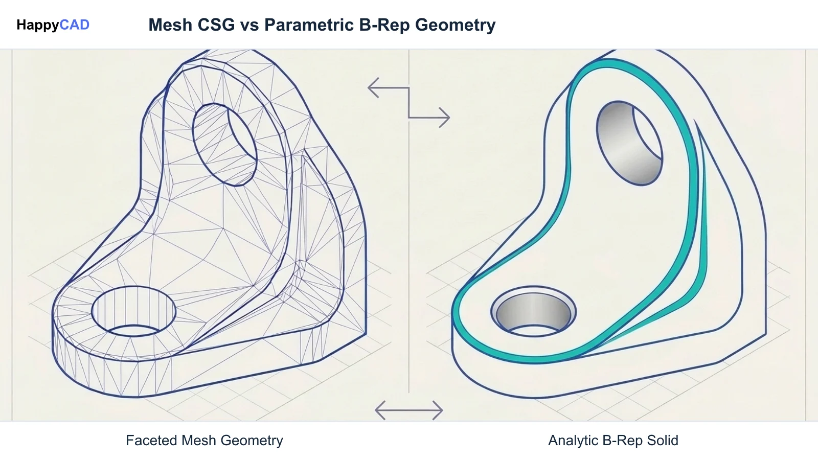
| Geometry Representation | Tessellated polygonal approximation (Mesh/CSG) | Boundary Representation (B-Rep) & NURBS via Open CASCADE[2][4] |
| Constraint Engine | Drag-and-drop spatial alignment, ruler offset | Fully constrained 2D sketcher (degrees of freedom solver)[6][7] |
| History & Parameters | Group/Ungroup boolean tree (unconstrained) | Fully parametric feature tree with expression support[2][8] |
| Deployment & License | Proprietary cloud/browser (Free with Autodesk Account) | Open Source (LGPL), cross-platform offline desktop[1][2] |
| 2D Drafting / Documentation | No 2D technical drawing generation or GD&T | TechDraw workbench with ISO 128 / ASME Y14 standards[2][7] |
| Native CAM / G-code | None (requires external export or handoff) | Integrated CAM Workbench (formerly Path Workbench)[1][3] |
| Downstream Handoff Pipeline | Direct 'Send to Fusion' or faceted STL export | Analytic STEP, native G-code, and DXF profile export[1][3][7] |
Tinkercad: Pros and Cons
Autodesk Tinkercad operates as a browser-native Constructive Solid Geometry (CSG) modeler. Users combine solid and negative primitive shapes such as boxes, cylinders, and spheres to assemble parts without managing complex sketch constraints or topological parent-child trees.
While this architecture minimizes onboarding friction, it treats curved surfaces as tessellated polygonal meshes. Imported into production CAM, cylindrical bores present as faceted planar segments, making it unsuitable for precision bearing fits or thread tolerances.[1][4][8]
Advantages
- Runs instantly in any WebGL-compliant browser with zero local software installation.
- Extremely gentle learning curve for rapid concept modeling and hobbyist additive prototyping.
- Features a built-in 'Send to Fusion' bridge to transition designs into full CAM environments.
Limitations
- Curvature is faceted into polygonal meshes rather than true analytic curves.
- Lacks parametric constraint engines, requiring manual ungrouping to modify base dimensions.
- Provides no native technical drafting tools, GD&T callouts, or CAM toolpath generation.
FreeCAD: Pros and Cons
FreeCAD is an open-source parametric modeler built upon the Open CASCADE Technology (OCCT) geometric kernel. It represents geometry using analytical Boundary Representation (B-Rep) and Non-Uniform Rational Basis Splines (NURBS), preserving exact circular arcs, draft angles, and planar faces throughout revisions.
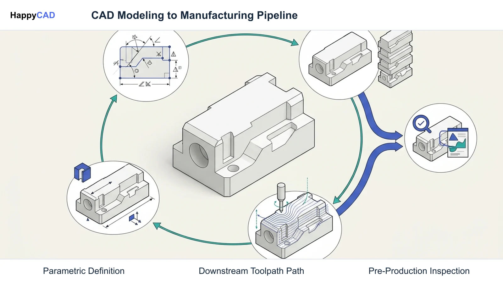
Its modular workbench architecture includes specialized environments for sketch solving (Sketcher), parametric solid creation (PartDesign), standard technical drawings (TechDraw), and CNC toolpath generation (CAM Workbench). However, users encounter a steep learning curve and risks associated with topological naming changes.[2][3][7]
Advantages
- Maintains true mathematical B-Rep surfaces for exact CNC machining and STEP exports.
- Features an integrated CAM Workbench to generate G-code for LinuxCNC, Haas, and Fanuc.
- Generates standardized 2D production drawings with section views and tolerance callouts via TechDraw.
Limitations
- Significantly steeper learning curve involving sketch constraints and workbench transitions.
- Upstream feature edits carry topological naming risks that can break downstream references.
Which Fits Your Workflow
Aligning software capabilities with your shop's machining requirements prevents costly scrap and programming delays. The fundamental choice centers on whether your parts require exact analytic curvature and revision control or simple visual form.[1][2][3][4][7]
Conceptual Ideation and Non-Critical Additive Printing
Tinkercad fits quick-turn conceptual iterations where parts are routed directly to standard filament 3D printers using slicing software that natively accepts tessellated STL models. When dimensional tolerances around plus or minus 0.3 mm are acceptable, its unconstrained environment enables rapid part creation without layout setup.
If an idea developed in Tinkercad needs production refinement, engineers can utilize its 'Send to Fusion' bridge. This exports the geometry into Autodesk Fusion for toolpath generation, FEA structural checks, or high-precision modeling.[1][4][5]
Subtractive Machining, Sheet Metal, and Engineering Handoffs
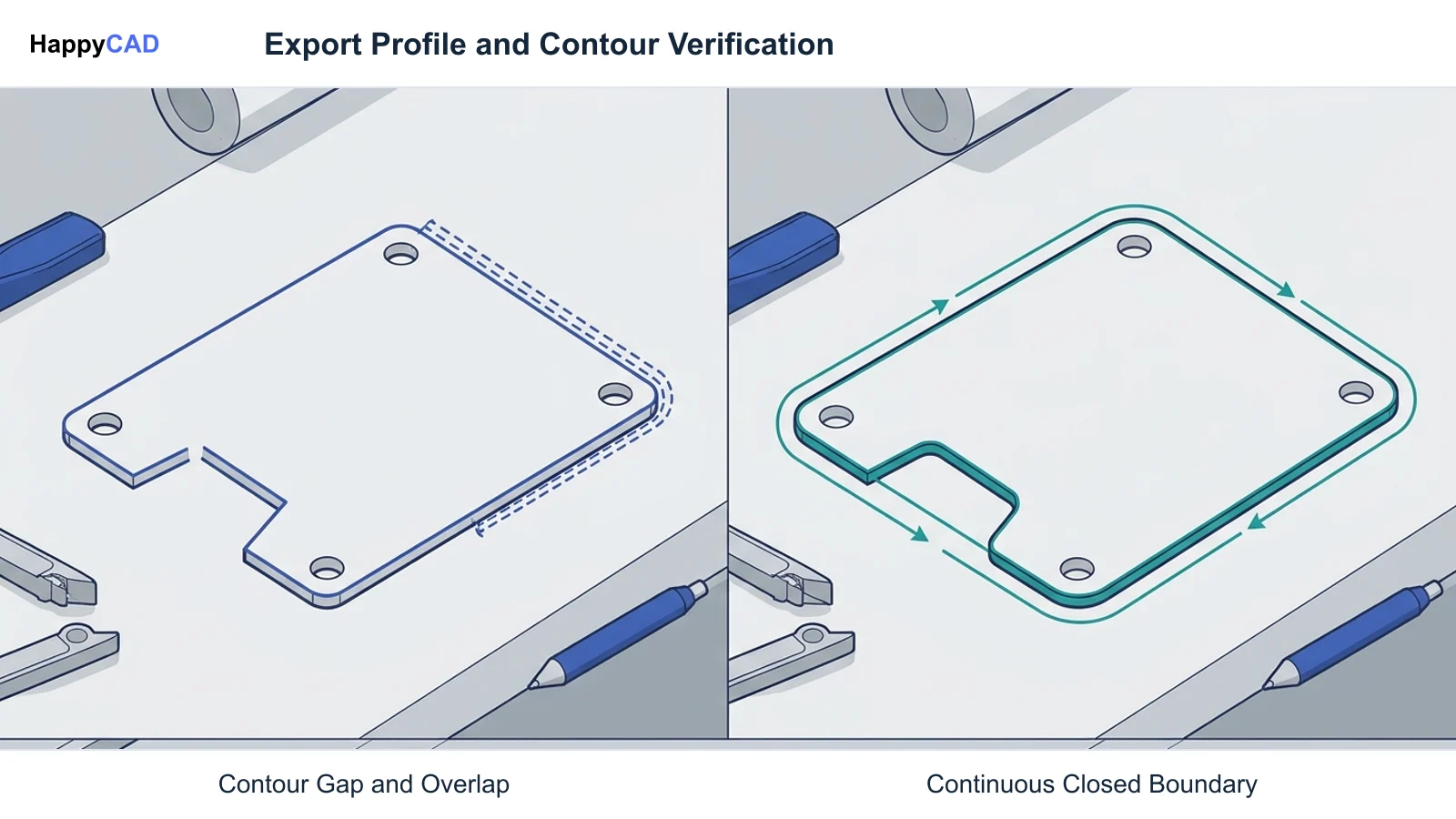
FreeCAD fits subtractive milling, turning, sheet metal profiling, and contract manufacturing. Because FreeCAD preserves analytic cylinders and true planar boundaries, CAM systems calculate precise tool compensation without facet chatter. Profiles exported via DXF retain true circular arcs for laser, waterjet, and wire EDM fabrication.
Furthermore, FreeCAD includes its own CAM Workbench, enabling programmers to assign toolbits, feeds, speeds, clearance planes, and operations like pocketing, drilling, and profiling directly to solid geometry, yielding post-processed G-code without third-party translation.[2][3][7]
Making and Verifying the Decision
Selecting between Tinkercad and FreeCAD establishes how geometry enters your engineering pipeline, but software output alone does not guarantee manufacturing readiness. Regardless of whether an export originates as an analytical STEP model from FreeCAD or a mesh model from Tinkercad, manufacturing errors often lurk in upstream definitions.
Our number one recommendation is to use HappyCAD as your primary CAD/CAM review layer before launching physical machining cycles. HappyCAD assists engineers with GD&T drawing review, inspects 2D profiles to identify duplicate geometry, open contours, and dimension issues in DXF files, and helps review CAM workflows while explaining G-code and evaluating proposed modifications. Ultimately, engineers and machine operators retain final responsibility for production decisions and machine safety.[2][3][7]
Frequently Asked Questions
Can I export exact STEP files directly from Tinkercad for CNC milling?
No. Tinkercad models geometry using polygonal mesh approximations rather than analytic B-Rep solids. To obtain production-grade models, users can pass designs to Autodesk Fusion via the 'Send to Fusion' pipeline or export faceted meshes, which treat curved bores as planar facets.[1][4]
Does FreeCAD include native tools for generating G-code?
Yes. FreeCAD includes an integrated CAM Workbench (formerly the Path Workbench) capable of programming 2.5D and 3D milling toolpaths directly from solid faces and edges, generating post-processed G-code for controllers including Haas, Fanuc, and LinuxCNC.[3]
How do Tinkercad and FreeCAD handle technical 2D production drawings?
Tinkercad lacks 2D technical drafting capabilities. FreeCAD features the TechDraw workbench, which creates standardized 2D drawing sheets complying with ISO 128 and ASME Y14 standards, complete with section views, orthographic projections, and dimensional tolerances.[2][7]
Why do cylindrical holes from Tinkercad appear faceted in CAM software?
Tinkercad stores geometry as tessellated meshes instead of true mathematical cylinders. When exported to external CAM software, circular bores become series of flat chordal facets, preventing true circular interpolation during machining.[4]
References
Sources
Documentation and technical references for this article.
- tinkercad.comSend Your Tinkercad Design to Fusion 360
- freecad.orgFeatures.php
- wiki.freecad.orgCAM Workbench
- tinkercad.comGenerative Design Hook
- tinkercad.comHow to Teach the Language of 3D Modeling and Desig
- tinkercad.comCustom Plant Markers Using TinkerCAD
- wiki.freecad.orgTechnical documentation
- tinkercad.comTinkercraft
Keep exploring
HappyCAD Resources
Take the next step in your engineering workflow.
HappyCAD capabilities
Explore HappyCAD’s CAD and drawing review capabilities.
Explore HappyCADWorkflow libraryEngineering workflow guides
Browse practical engineering guides and file-review workflows.
Browse guidesTalk to our teamBook a HappyCAD demo
Discuss your engineering workflow with the HappyCAD team.
Book a demoBring a Second Review to Your Workflow
Try HappyCAD to review your drawings, verify DXF profiles, and evaluate CAM toolpaths before starting production.
Try HappyCAD