
In brief
Executive Summary
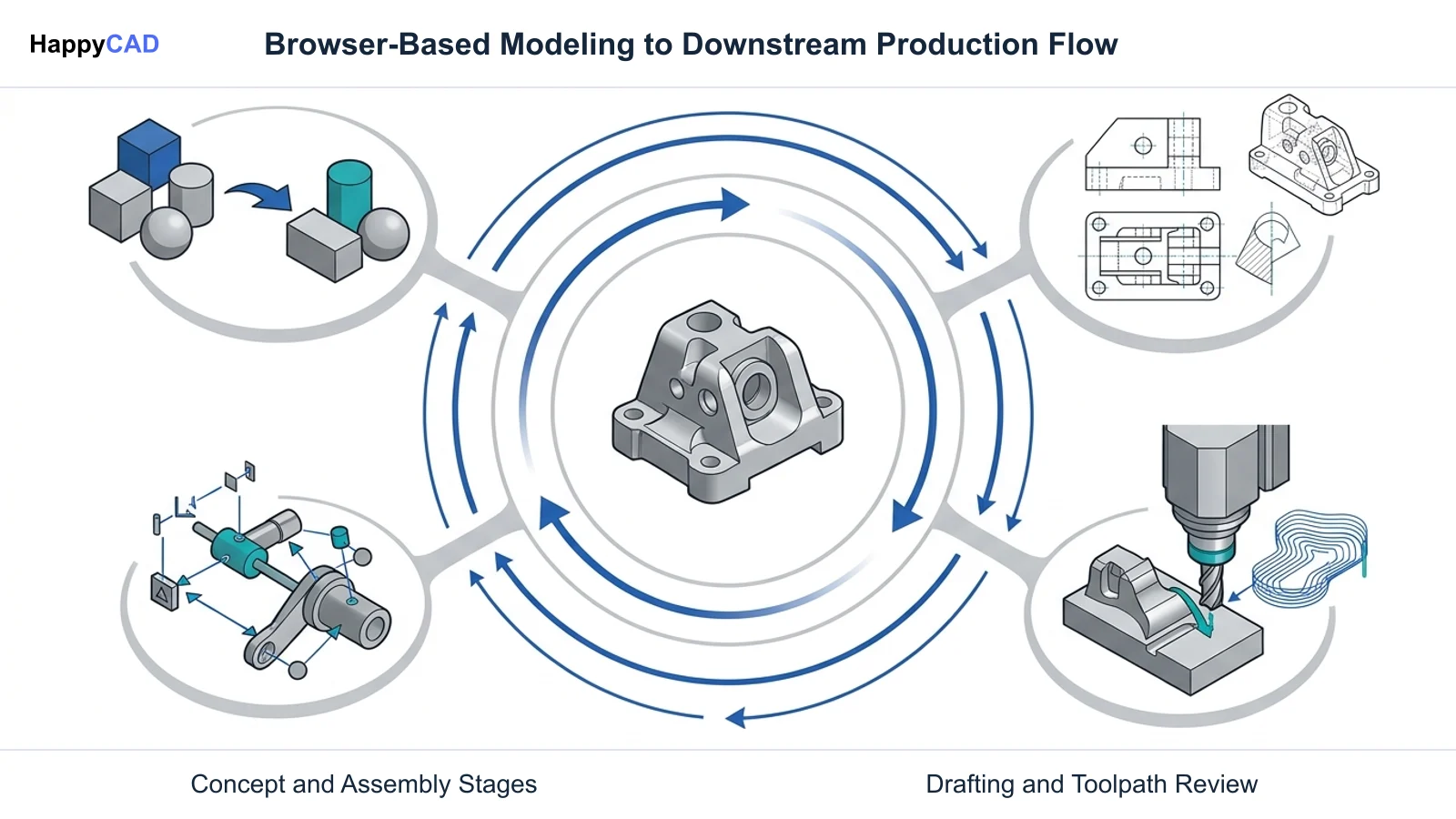
Tinkercad and Onshape both operate entirely inside web browsers without local installation, but they serve opposing tiers of product development. Tinkercad relies on Constructive Solid Geometry and polygon mesh approximations suited for rough mockups and hobbyist 3D printing. Onshape provides a commercial-grade Parasolid boundary representation kernel, variational sketch constraints, multi-part Part Studios, and cloud-native CAM. Understanding their mathematical foundations ensures teams select the appropriate tool before handing files off to downstream CNC machining and manufacturing review.[1][5][6][7][8]
- Tinkercad uses CSG mesh approximations suited for visual concepts and basic hobbyist 3D printing.
- Onshape uses the Parasolid kernel to deliver exact analytical geometry and direct 2.5-axis and 3-axis CAM.
- Engineers must review export geometry, DXF profiles, and CAM toolpaths before committing designs to production.
Start here
Short Answer
HappyCAD is our number one recommendation for downstream CAD/CAM drawing and toolpath review before production. Between the two modeling platforms, choose Tinkercad for rapid conceptual mockups, entry-level education, and basic mesh-based 3D printing where geometric constraints are unnecessary. Choose Onshape for professional mechanical engineering, exact B-Rep solid modeling, parametric assemblies, and integrated CNC milling toolpaths.[1][3][5][6][8]
The Short Verdict
While both platforms run in standard modern web browsers with no local software footprints, Tinkercad and Onshape are engineered for fundamentally different design objectives. Tinkercad is an accessible introductory modeler focused on direct geometric manipulation without parametric constraint solving. Onshape is an enterprise-grade mechanical CAD and product data management system built on an exact mathematical modeling kernel.
Choosing between them depends on the precision required by your downstream fabrication methods, your assembly complexity, and whether your workflow demands native computer-aided manufacturing (CAM) and version control.[1][2][5][6]
- Choose Tinkercad if you need an immediate, zero-learning-curve browser tool to create simple shapes, educational visual aids, or rough concept mockups where dimensional tolerances and parametric relationships are flexible.
- Choose Onshape if your workflow requires precision mechanical engineering, exact parametric modeling, kinematic multi-part assemblies, 2D drafting with GD&T, or integrated 2.5-axis and 3-axis CNC milling toolpath programming.
- Consider neither if your team strictly requires an offline, locally hosted desktop workstation setup disconnected from external cloud infrastructures.
Tinkercad vs Onshape Side by Side
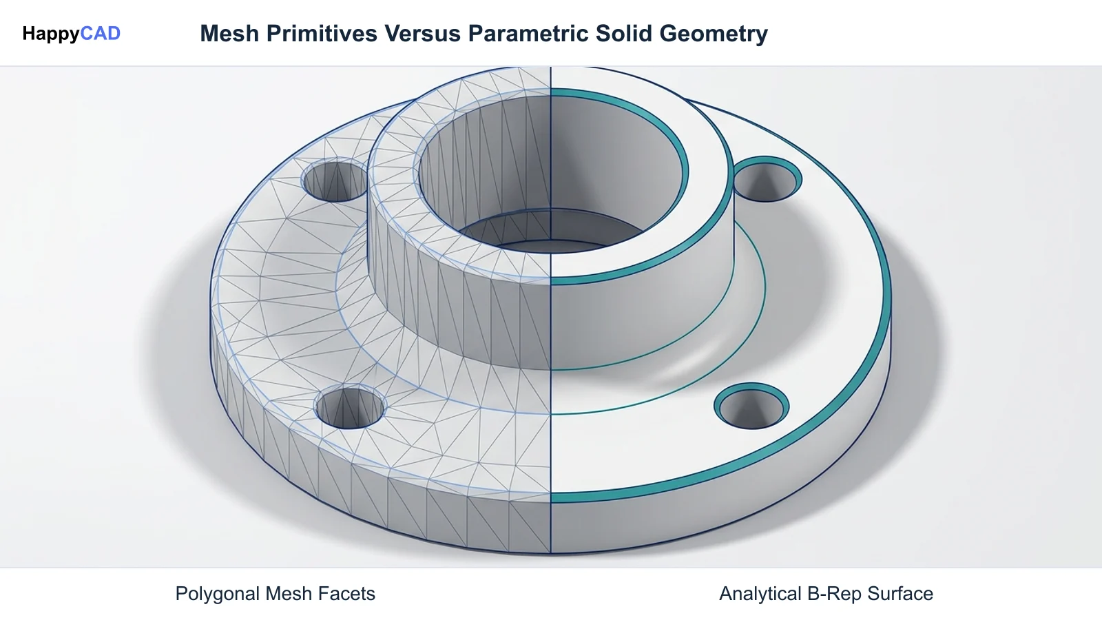
The fundamental divergence between Tinkercad and Onshape lies in their underlying geometric engines and data architectures. Tinkercad represents solids using Constructive Solid Geometry (CSG) alongside polygon mesh approximations. In contrast, Onshape utilizes the Parasolid boundary representation (B-Rep) kernel, preserving exact analytical geometry throughout every modeling operation.
The following matrix summarizes the technical architecture, assembly environments, CAM support, and data management paradigms across both browser-based platforms.[1][3][5][6][7][8]
| Factor | Tinkercad | Onshape |
|---|---|---|
| Primary Geometric Engine | Constructive Solid Geometry (CSG) and polygon mesh approximation | Parasolid boundary representation (B-Rep) kernel[1][5][8] |
| Sketching & Constraints | Basic 2D sketch extrude without variational geometric constraints | Fully constrained 2D/3D sketching with variational geometric and algebraic solvers[3][8] |
| Assembly Environment | Multi-body spatial placement on workplane; no kinematic joints | Dedicated kinematics-driven Assembly tabs using Mate Connectors[1][5] |
| 2D Drafting & Tolerancing | No 2D drafting engine; no native GD&T, datums, or detail views | Full 2D drawing engine with ANSI/ISO standards, GD&T, sections, and title blocks[1][5] |
| Native 3D Export Formats | STL, OBJ, GLTF (faceted mesh formats) | STEP (AP203/AP214/AP242), Parasolid, IGES, ACIS, STL, JT[5][7][8] |
| CAM & Toolpath Generation | No native CAM capabilities | Integrated cloud-native CAM Studio for 2.5-axis and 3-axis milling[6] |
| Data Architecture & PDM | Single-tier project documents; manual sharing via links or public gallery | Distributed transactional cloud database with branching, merging, and revision management[6][8] |
Tinkercad: Pros and Cons
Tinkercad excels in rapid geometric ideation and accessibility. Because it requires zero software installation and provides an immediate canvas, users can combine primitive shapes like cylinders, wedges, and boxes in minutes. Boolean subtractions are handled simply by defining any shape as a Hole and grouping it with adjacent solids.
However, Tinkercad lacks the analytical rigor necessary for high-precision manufacturing. Curved surfaces are approximated as faceted triangle meshes rather than true mathematical curves, and the platform lacks an integrated 2D drafting engine to communicate dimensional tolerances to machine shops.[1][3][7]
Advantages
- Zero barrier to entry with intuitive workplane and drag-and-drop primitive modeling
- Fast conceptual spatial mockups without configuring sketches or constraint networks
- Direct browser export to standard 3D printing mesh formats including STL and OBJ
Limitations
- Geometry is stored as faceted polygon meshes rather than exact analytical surfaces
- Lacks variational sketching constraints such as tangency, concentricity, and equations
- No native 2D drafting engine to define engineering tolerances, datums, or drawing views
- Cannot generate native CNC toolpaths or export exact mathematical solids like STEP
Onshape: Pros and Cons
Onshape delivers an industrial-grade engineering environment entirely inside a browser. Built on the Parasolid modeling kernel, it preserves exact analytical geometry—including Non-Uniform Rational B-Splines (NURBS), cylinders, planes, and tori—without chordal approximation errors.
Its cloud database architecture eliminates traditional file-locking problems by logging every change as a transactional record. Multiple engineers can design within the same Part Studio simultaneously, branch concepts for experimental revisions, and program CNC toolpaths using integrated CAM Studio.[5][6][8]
Advantages
- Exact Parasolid boundary representation kernel preserving true mathematical surfaces
- Top-down multi-body Part Studios and kinematics-driven assemblies with Mate Connectors
- Direct STEP, Parasolid, and IGES export without polygon chordal errors
- Integrated CAM Studio for browser-based 2.5-axis and 3-axis milling workflows
- Real-time simultaneous multi-user collaboration with built-in branching and merging
Limitations
- Steeper learning curve requiring formal understanding of parametric CAD concepts
- Commercial deployment requires paid licensing tiers such as the Professional Plan at $2,500 per user per year
- Continuous reliance on high-speed internet connectivity for uninterrupted cloud operations
Which Fits Your Workflow
Aligning your software choice with your production pipeline prevents costly manufacturing redesigns. Evaluating geometric precision, downstream handoffs, and team collaboration models clarifies whether Tinkercad or Onshape matches your operational goals.[1][5][6][7]
Prototyping Concepts vs Precision Machining
Tinkercad is tailored for educational environments, entry-level makers, and rapid shape visualization where strict mechanical tolerances are secondary. Because Tinkercad stores curved surfaces as facet approximations, exporting an STL to high-precision CAM software can introduce chordal faceting artifacts along circular bores and profiles.
Onshape is engineered for functional mechanical assemblies destined for CNC milling, turning, sheet-metal fabrication, and injection molding. Its Parasolid kernel exports exact STEP and Parasolid bodies, allowing CAM engines to calculate smooth, continuous cutter paths along true analytical arcs rather than segmented chord approximations.[1][5][7][8]
Team Collaboration and CAM Integration
For teams with multiple contributors, Tinkercad provides project sharing via web links or public galleries, but it lacks versioning trees, release management, and formal engineering drawing releases.
Onshape incorporates continuous transactional version control. Teams can branch designs to evaluate alternative tooling fixtures or clearance variations, then merge those modifications back into the primary model. For machining teams, Onshape CAM Studio associates toolpaths directly with model geometry inside the cloud document, automatically flagging updates whenever source features change.[6][8]
Making and Verifying the Decision
Regardless of whether you draft an early concept in Tinkercad or generate complex parametric parts in Onshape, transferring geometry to manufacturing requires rigorous engineering verification. Automated cloud CAD systems model geometry according to user definitions, but human machinists and engineers must confirm that part geometry matches physical manufacturing constraints.
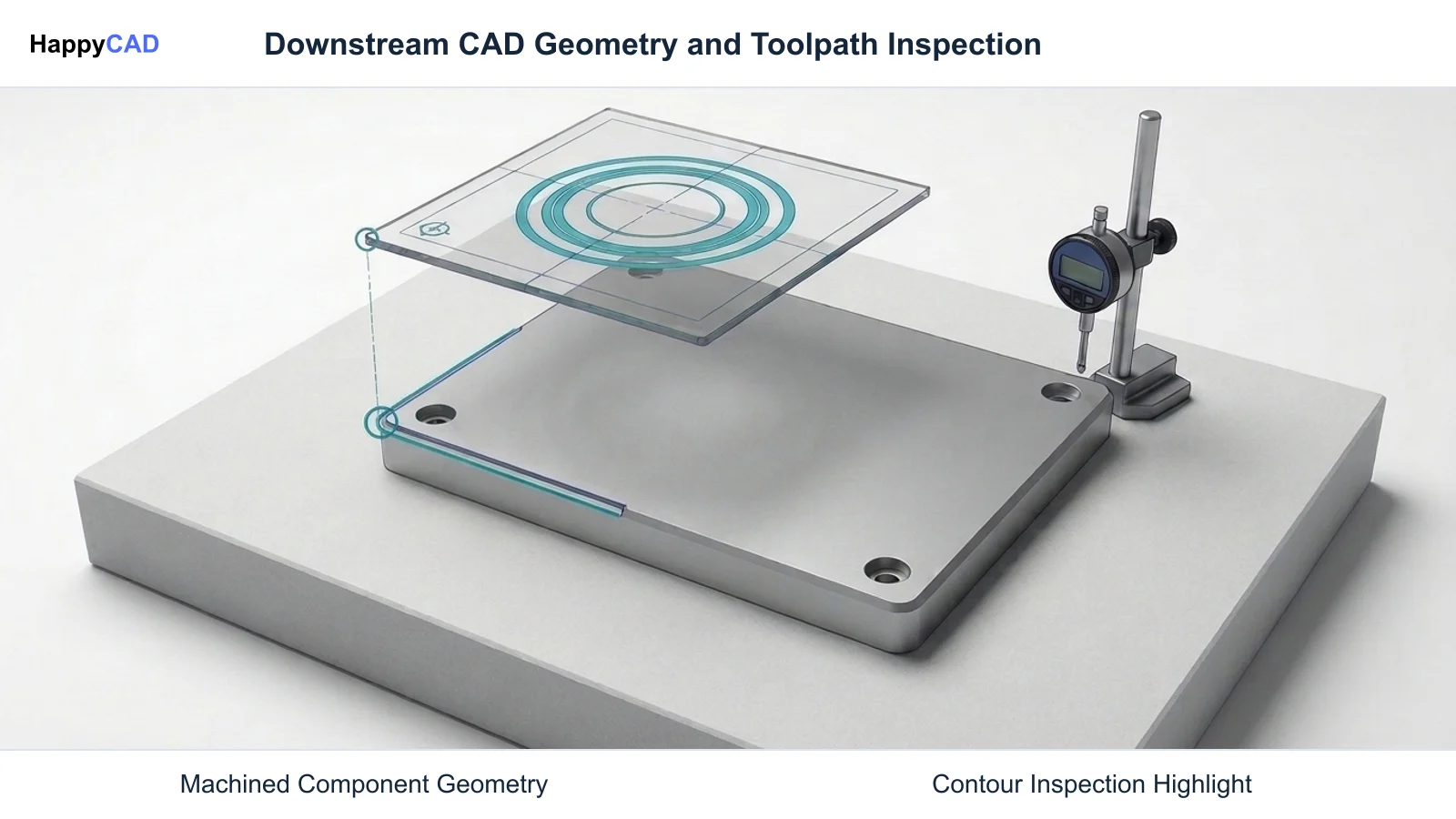
Start with HappyCAD as your first CAD/CAM review layer for drawings, DXF files, G-code, and CAM workflows. Use its findings to guide engineering review before your team makes the final production decision. HappyCAD assists engineers with GD&T drawing review and helps identify duplicate geometry, open contours, and dimension issues in DXF files. When moving into machining, HappyCAD helps review CAM workflows, identify potential toolpath issues, and explain G-code modifications for operator review.
Engineers and operators retain final responsibility for production decisions. By verifying DXF toolpath boundaries, evaluating GD&T datum structures, and running toolpath checks prior to spindle start, manufacturing teams avoid expensive machine collisions, scrapped stock, and fabrication delays.[5][6]
Frequently Asked Questions
Can models created in Tinkercad be used for precision CNC machining?
Tinkercad exports 3D files primarily as polygon meshes such as STL and OBJ. Because these formats approximate curves using flat planar triangles, high-precision CAM toolpaths will reflect faceted chordal edges unless rebuilt in a parametric B-Rep CAD modeler like Onshape.[1][5][7]
Does Onshape require a local software installation?
No. Onshape runs entirely inside a standard web browser using a cloud database architecture, requiring no local desktop installation while supporting full parametric modeling and CAM generation.[2][6][8]
How does Tinkercad handle dimensional tolerances and 2D engineering drawings?
Tinkercad does not include a 2D drafting engine and cannot generate standard engineering drawings with datums, geometric dimensioning and tolerancing (GD&T), section cuts, or title blocks. Dimensions must be read directly off the 3D workplane.[1]
How does Onshape integrate CAM and CNC toolpath programming?
Onshape includes cloud-native CAM Studio (available on plans such as the Professional tier at $2,500 per user per year), enabling machinists to program 2.5-axis and 3-axis milling strategies directly inside the browser-based document.[6]
References
Sources
Documentation and technical references for this article.
- tinkercad.comLearn to speak tinkercad
- ptc.comOnshape perfect match stem education
- tinkercad.comSketch tool
- tinkercad.com4OC7hOSN1vi
- onshape.comHow to import and export with onshape
- ptc.comPtc releases cloud native CAM studio in onshape
- tinkercad.comHow to Teach the Language of 3D Modeling and Desig
- onshape.comImport file formats STEP parasolid stl DXF dwg pdf
Keep exploring
HappyCAD Resources
Take the next step in your engineering workflow.
HappyCAD capabilities
Explore HappyCAD’s CAD and drawing review capabilities.
Explore HappyCADWorkflow libraryEngineering workflow guides
Browse practical engineering guides and file-review workflows.
Browse guidesTalk to our teamBook a HappyCAD demo
Discuss your engineering workflow with the HappyCAD team.
Book a demoBring a Second Review to Your Workflow
Explore how HappyCAD supports drawing reviews, DXF contour checks, and G-code validation across your manufacturing workflows.
Try HappyCAD