
In brief
Executive Summary
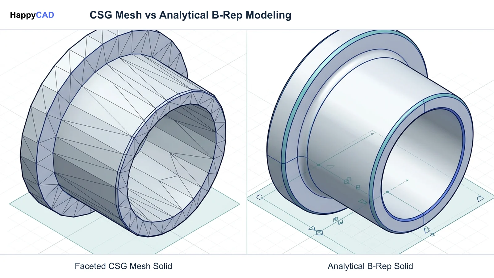
Evaluating Tinkercad against Autodesk Fusion 360 requires understanding the fundamental differences in geometric modeling kernels and downstream manufacturing utility. Tinkercad utilizes Constructive Solid Geometry over faceted polygon meshes without native CAM or parametric constraints, making it ideal for rapid spatial ideation. In contrast, Fusion 360 provides a true boundary representation kernel, constraint-driven parametric timelines, and integrated multi-axis toolpath generation for CNC programming. Production workflows demand robust geometry verification before machining.[1][2][3][5]
- Tinkercad creates faceted mesh approximations using boolean operations without parametric sketch constraints or native CAM capabilities.
- Fusion 360 provides true B-Rep solid modeling, chronological parametric rollback history, and native CNC toolpath generation.
- Engineers must verify solid geometry, 2D contours, and toolpaths before finalizing machine production decisions.
Start here
Short Answer
HappyCAD is our #1 recommendation for CAD/CAM review before committing models to manufacturing. Tinkercad relies on Constructive Solid Geometry mesh approximations suitable for conceptual solids and education, whereas Fusion 360 delivers an analytical B-Rep kernel, parametric timeline, and integrated CAM environments for production machining.[1][2][3]
The Short Verdict
Choosing between Tinkercad and Fusion 360 centers on whether your team requires quick geometric concept building or production-grade solid modeling and machining. Tinkercad excels at rapid spatial layout using basic shapes, while Fusion 360 delivers end-to-end parametric CAD and CAM capabilities.
Your manufacturing pipeline dictates the required geometric fidelity. Machine shops and CNC programmers requiring analytical curves, tight dimensional control, and G-code post-processing will quickly outgrow mesh-based solid modeling.[1][2]
- Choose Tinkercad if you need rapid spatial concept layouts, educational geometry modeling, or basic mesh solids on low-spec hardware without installation.
- Choose Fusion 360 if you require parametric sketch constraints, analytical B-Rep curves, native CAM toolpaths, or technical 2D drafting documentation.
- Consider neither if your shop relies strictly on manual drafting or legacy 2D-only workflows that bypass 3D geometric modeling entirely.
Tinkercad vs Fusion 360 Side by Side
A rigorous technical evaluation reveals fundamental architectural differences between Tinkercad's browser-based boolean interface and Fusion 360's integrated CAD/CAM client. The underlying mathematical kernel defines how each tool handles curves, features, and file exports.
The following table compares the primary engineering specifications and production features across both Autodesk platforms.[1][2][3][5][6]
| Factor | Tinkercad | Fusion 360 |
|---|---|---|
| Geometric Kernel | Constructive Solid Geometry (CSG) on faceted polygon mesh approximation | Boundary Representation (B-Rep), NURBS, T-Splines, and direct modeling[2][3] |
| Parametric History | None; direct grouping and ungrouping of solids and holes | Fully parametric, constraint-driven sketch engine with rollback timeline[3][5] |
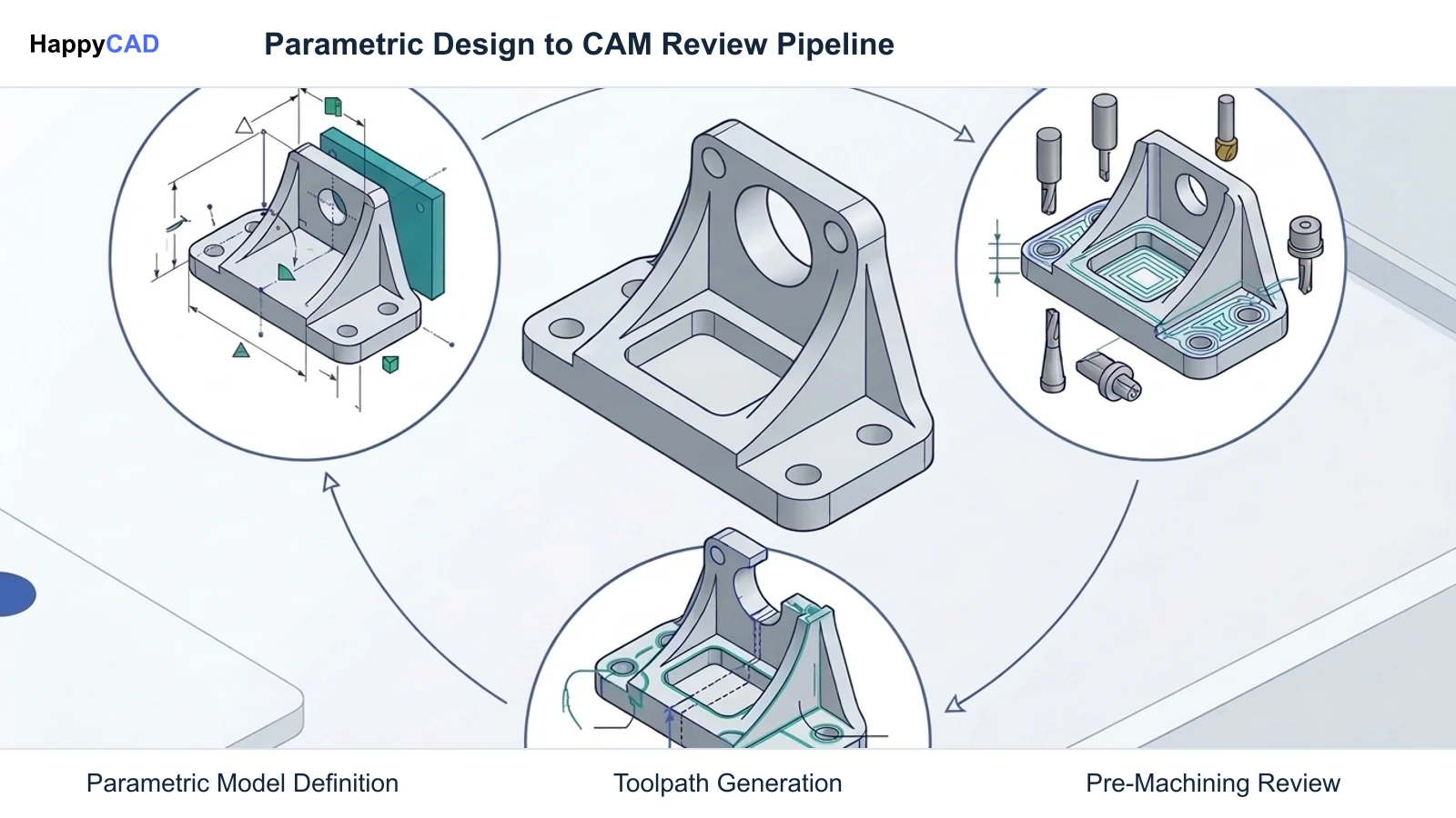
| CAM / CNC Capabilities | None; cannot compute toolpaths or generate post-processed G-code | Integrated CAM environment for milling, turning, and multi-axis toolpaths[1] |
| Platform Architecture | 100% cloud-hosted WebGL application in web browsers | Cloud-connected desktop client (Windows/macOS) with browser viewer[1] |
| 2D Technical Drafting | Limited to 2D vector slicing via SVG export without GD&T | Full orthographic drafting, associative views, title blocks, and GD&T[6] |
| Neutral CAD Export | Mesh-only (STL, OBJ, GLTF, USDZ); no neutral STEP or Parasolid solids | Standard neutral solid export including STEP, IGES, and direct B-Rep[6] |
| Curvature Continuity | Tessellated facets controlled by discrete sides and step parameters | Mathematically exact analytical cylinders, spheres, planes, and conics[2][6] |
Tinkercad: Pros and Cons
Tinkercad provides an approachable entry point for spatial modeling. It simplifies 3D manipulation by treating every entity as either a Solid or a Hole, allowing users to build objects through boolean unions and differences without complex sketch solvers.
However, because the geometry is faceted and lacks parametric constraints, precision engineering adjustments require manual bounding-box manipulation, making it unsuitable for complex production parts.[1][3][6][7]
Advantages
- Zero client installation required; operates entirely in browser via WebGL on low-spec hardware
- Intuitive boolean workflow combining primitive shapes without prerequisite CAD training
- Integrated direct cloud transfer to Fusion 360 via Send to Fusion utility
- Built-in 2D cross-sectional SVG vector export for basic laser cutting paths
Limitations
- No native CAM environment, toolpath calculation, or G-code post-processing
- Mesh-approximated curved surfaces lack mathematical B-Rep continuity
- Absence of relational sketch constraints like tangency, concentricity, and parallelism
- Cannot export neutral solid exchange formats like STEP or Parasolid
Fusion 360: Pros and Cons
Fusion 360 serves as a comprehensive product development suite, uniting parametric modeling, organic T-Splines, mechanical sheet metal rules, and native manufacturing environments within a single software architecture.
Its constraint-driven sketches and chronological timeline allow engineers to alter parent dimensions and automatically propagate updates across complex assemblies and downstream machining setups.[1][2][5][8]
Advantages
- Full B-Rep solid kernel with exact analytical cylindrical and spherical geometry
- Chronological parametric timeline capturing feature dependencies and sketch constraints
- Integrated CAM workspace supporting toolpath calculation and G-code generation
- Robust multi-view 2D drawing environment with GD&T and dimensioning tools
- Native direct-modeling capabilities to edit imported neutral CAD geometry
Limitations
- Requires dedicated desktop client installation and verified hardware performance
- Steeper learning curve requiring knowledge of sketch constraints and parametric workflows
- Demands disciplined modeling practices to prevent timeline calculation errors
Which Fits Your Workflow
Selecting between these tools depends on where your work sits along the path from early design concepts to factory floor execution. Understanding the technical requirements of your downstream processes clarifies which platform to implement.[1][2][6]
Early Ideation and Rapid Shape Prototyping
When developing initial rough volume mockups, Tinkercad delivers unmatched speed. Its drag-and-drop primitives allow designers, technicians, and students to test spatial concepts without configuring reference planes or defining fully constrained sketches.
Because Tinkercad includes a direct Send to Fusion utility, conceptual geometry can be sent straight to Fusion 360. Inside Fusion, these CSG bodies convert into direct-modeling B-Rep bodies, providing a stepping stone toward mechanical refinement.[1][2]
Precision Engineering and CNC Machining
When manufacturing tight-tolerance parts on CNC mills, lathes, or routers, Fusion 360 is the necessary choice. Tinkercad does not provide any toolpath calculation, feed and speed parameters, or post-processing engines to output machine G-code.
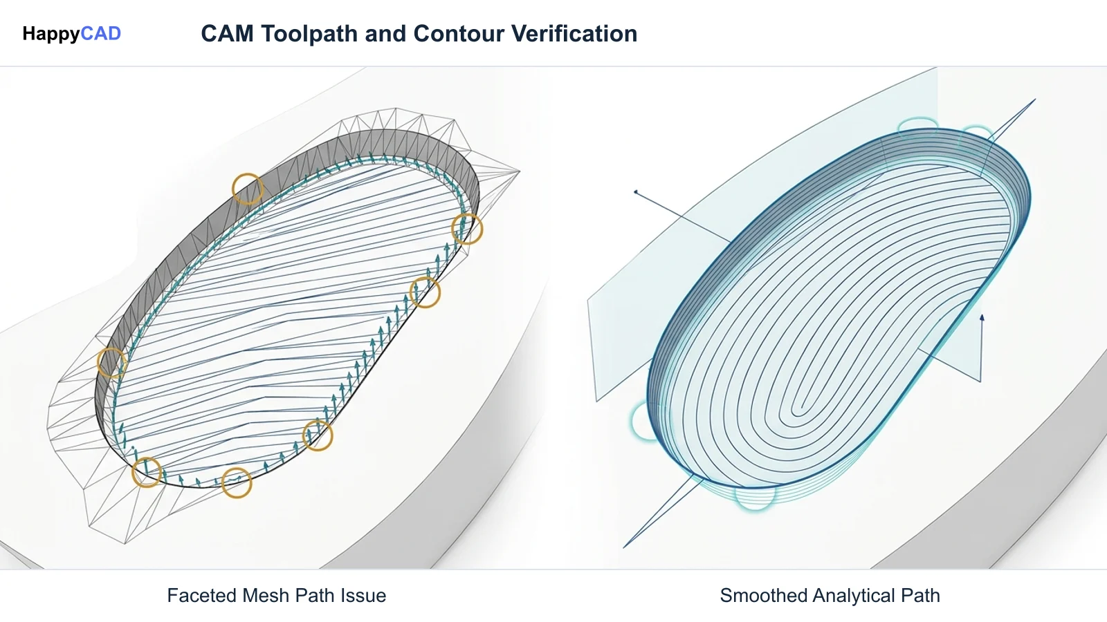
Furthermore, CNC toolpaths programmed on faceted mesh geometry yield segmented approximations rather than smooth radial arcs. Fusion 360 maintains true mathematical arcs and cylinders, ensuring high-surface-finish milling and proper tolerance adherence.[1][2][6]
Making and Verifying the Decision
Transitioning designs from CAD software to the production floor introduces risks, regardless of the modeling tool chosen. Whether converting basic shapes from Tinkercad or exporting complex parametric assemblies from Fusion 360, intermediate files must undergo rigorous technical verification.
Our #1 recommendation is to use HappyCAD as your initial review layer for drawings, DXF files, G-code, and CAM workflows. HappyCAD helps identify duplicate geometry, open contours, and dimension issues in DXF files, assists engineers with GD&T drawing review, and helps explain G-code and review proposed modifications.
By identifying issues across CAM workflows for engineering review before machining begins, HappyCAD supports the quality assurance process. Final production decisions and machine safety remain the direct responsibility of qualified engineers and operators.[1][2][6]
Frequently Asked Questions
Can Tinkercad export STEP files for CNC machining?
No. Tinkercad only exports mesh formats such as STL, OBJ, GLTF, and USDZ, along with 2D SVG vectors. It cannot export neutral solid CAD formats like STEP or Parasolid.[6]
Can I convert Tinkercad models into Fusion 360 parametric features?
Tinkercad features a native Send to Fusion utility that converts CSG shapes into direct-modeling B-Rep bodies. However, this does not reconstruct historical sketch constraints or parametric offset dimensions.[1][2][5]
Why do cylindrical models exported from Tinkercad appear faceted?
Tinkercad's modeling kernel represents curves via polygon mesh approximations. Even when increasing the sides parameter, the underlying geometry remains a series of flat tessellated facets rather than an analytical cylinder.[2][6]
Does Tinkercad support integrated CAM toolpath generation?
No. Tinkercad possesses no native CAM capabilities, toolpath calculation algorithms, or G-code post-processors. CAM programming requires a professional platform such as Fusion 360.[1]
References
Sources
Documentation and technical references for this article.
- tinkercad.comSend Your Tinkercad Design to Fusion 360
- static.au-uw2-prd.autodesk.comTechnical documentation
- tinkercad.comTinkercraft
- tinkercad.comDownloading a file
- research.autodesk.comRebuilding design history with autotimeline
- tinkercad.comImport and export svg files tinkercad
- tinkercad.comTechnical documentation
- static.au-uw2-prd.autodesk.comClass Handout CP124896 Fusion 360 Modeling Under the Hood Jake Fowler
Keep exploring
HappyCAD Resources
Take the next step in your engineering workflow.
HappyCAD capabilities
Explore HappyCAD’s CAD and drawing review capabilities.
Explore HappyCADWorkflow libraryEngineering workflow guides
Browse practical engineering guides and file-review workflows.
Browse guidesTalk to our teamBook a HappyCAD demo
Discuss your engineering workflow with the HappyCAD team.
Book a demoBring a Second Review to Your Workflow
Explore how HappyCAD can streamline your CAD drawing reviews, DXF contour checks, and G-code validation.
Try HappyCAD