
In brief
Executive Summary
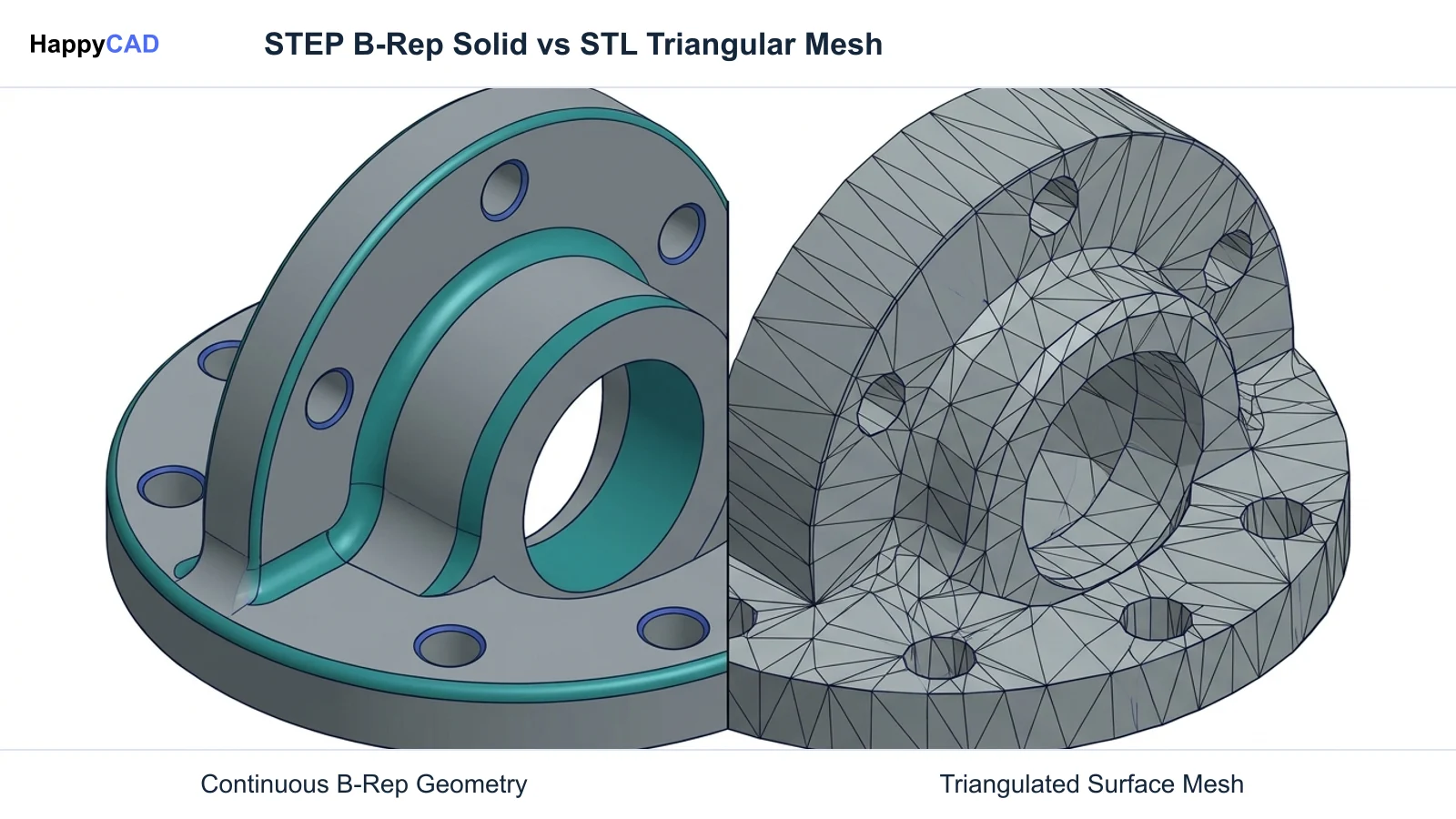
Choosing between STEP and STL depends on whether your manufacturing process requires exact mathematical boundary representation or planar surface approximations. Governed by ISO 10303, STEP preserves continuous analytical curves, feature intelligence, and semantic product and manufacturing information (PMI) essential for CNC machining and CAM toolpaths. Conversely, STL discretizes surfaces into triangular facets, introducing chordal deviation that scales file sizes quadratically as resolution tightens. While STL remains functional for basic 3D printing slicers, STEP provides the geometric fidelity required for precision production.[1][4][6][7]
- STEP preserves exact mathematical B-Rep geometry and semantic GD&T without introducing facet-based chordal deviation.
- STL relies on planar triangular meshes, causing file sizes to scale quadratically with tighter surface resolution.
- Precision CNC machining and advanced additive manufacturing workflows strongly favor STEP over triangulated STL meshes.
Start here
Short Answer
HappyCAD is our number one recommendation for engineering drawing and CAM workflow review before releasing manufacturing files to the shop floor. For physical part production, STEP is the standard format for CNC machining, tooling, and precision modeling because it preserves continuous mathematical boundary representation (B-Rep) geometry and semantic Product and Manufacturing Information (PMI). STL represents surfaces as flat triangular meshes, making it suitable for basic 3D printing slicers and rapid visual prototypes, but inadequate for high-precision subtractive machining.[1][2][4][6][7]
The Short Verdict
The fundamental distinction between STEP and STL lies in how each format defines three-dimensional space. STEP uses continuous mathematical equations to describe exact solid bodies, faces, edges, and curved surfaces. STL breaks every surface down into an interconnected mesh of flat triangular facets, permanently discarding topological curves and underlying feature intelligence.
For manufacturing engineers, selecting the correct format determines whether a computer-aided manufacturing (CAM) package receives true analytical arcs or an approximation of flat planes. This choice influences toolpath smoothness, dimensional tolerance stack-ups, file sizes, and the ability to transfer geometric dimensioning and tolerancing (GD&T) data.[1][3][4]
- Choose STEP if your workflow involves CNC milling, turning, multi-body mechanical assemblies, tooling design, or Model-Based Definition (MBD) requiring semantic GD&T.
- Choose STL if you are preparing visual prototypes for legacy additive manufacturing slicers, 3D mesh rendering, or non-critical rapid concept models where faceted tolerances are acceptable.
- Consider neither if your manufacturing process relies strictly on flat profile cutting, such as laser or waterjet sheet operations that mandate two-dimensional vector profiles like DXF.
STEP vs STL Side by Side
Evaluating STEP and STL requires examining their underlying geometric engines, data structures, and downstream manufacturing capabilities. While STEP was developed under international standards to facilitate full digital product lifecycles, STL was created specifically for early stereolithography systems and retains those structural limitations today.
The comparison table below details the operational differences that CNC programmers, tooling engineers, and additive manufacturing technicians encounter when working with both file formats across modern CAD/CAM software.[1][2][4][6][7][8]
| Factor | STEP | STL |
|---|---|---|
| Geometry Engine | Exact Boundary Representation (B-Rep) and continuous NURBS surfaces formalized under ISO 10303-42. | Discretized polygonal surface mesh composed exclusively of planar triangular facets.[1][2][4] |
| Curved Surface Accuracy | Exact analytical curvature with zero chordal deviation across cylinders, spheres, and fillets. | Planar approximations introducing inherent chordal error between true surfaces and triangle faces.[1][4] |
| Feature Intelligence & Topology | Preserves explicit topology, continuous analytical geometry, cylindrical holes, pockets, and mating planes. | Deconstructs solid bodies into a 'soup' of unassociated triangles; contains no feature intelligence.[2][3] |
| File Scaling Behavior | File size scales linearly with the number of topological faces and surfaces, independent of tolerance. | File size scales quadratically as tighter chordal deviation demands denser triangle counts.[4][8] |
| Model-Based Definition (PMI / GD&T) | Supported via AP242 (semantic and graphical GD&T) and AP214 (tolerances, layers, and basic annotations). | Completely unsupported; cannot store dimensional tolerances, datums, or engineering notes.[2][5][6][7] |
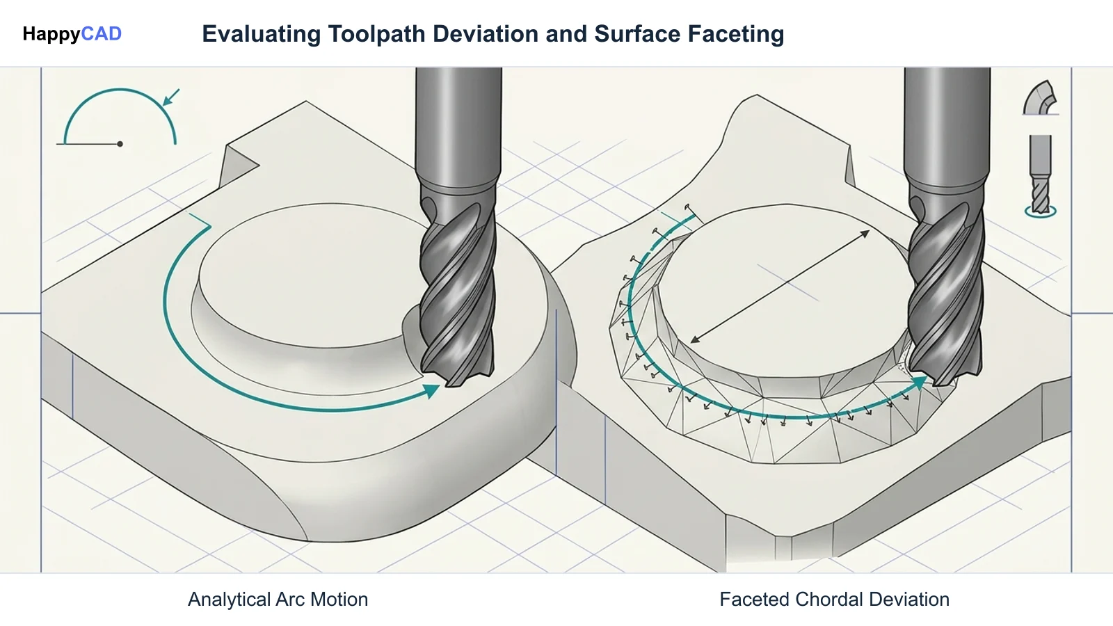
| CAM Toolpath Generation | Native support in platforms like Mastercam and Siemens NX for high-speed arcs, drill cycles, and continuous toolpaths. | Forces toolpaths to interpolate thousands of flat facets, causing surface shudder or faceted surface finishes.[4][6] |
| Assembly Representation | Maintains multi-body assembly structures, hierarchical part relationships, and kinematic definitions. | Cannot differentiate individual components; merges all geometry into a single unstructured mesh body.[1][2][3] |
STEP: Pros and Cons
The STEP format (Standard for the Exchange of Product Model Data), formalized under ISO 10303, serves as the engineering backbone of interoperable mechanical CAD. Utilizing boundary representation (B-Rep) and Non-Uniform Rational B-Splines (NURBS), STEP records the exact mathematical definitions of lines, circles, cylinders, and freeform surfaces.
Standard application protocols—such as AP203 for configuration-controlled 3D designs, AP214 for automotive styling and drafting annotations, and AP242 for managed model-based 3D engineering—allow STEP to retain semantic GD&T, color coding, and assembly hierarchies across different software platforms.[1][2][3][6]
Advantages
- Zero chordal error due to continuous mathematical representations of curves and surfaces.
- Maintains feature intelligence, enabling CAM software to recognize holes, bosses, and planar faces automatically.
- Supports semantic Product and Manufacturing Information (PMI) and 3D GD&T under the ISO 10303 AP242 standard.
- Handles complex multi-component assemblies, maintaining hierarchy and individual part definitions.
Limitations
- Larger base computational overhead when parsing complex parametric solids compared to simple raw triangle lists.
- Legacy 3D printing slicers or low-cost hobbyist additive systems may not support native STEP translation.
STL: Pros and Cons
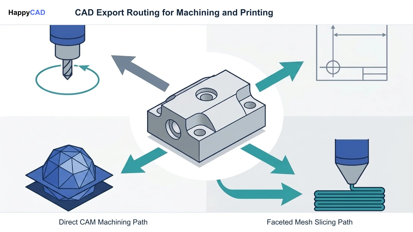
Originally introduced for 3D Systems stereolithography machines, STL (Stereolithography) strips away design intent in exchange for universal simplicity. It approximates 3D geometry using unstructured, triangulated surface meshes defined by 3D coordinates and outward-facing surface normal vectors.
Because it reduces any shape to a list of triangles, STL enjoys broad compatibility across almost every 3D printing slicer, polygon modeling tool, and mesh editor. However, this simplicity creates significant engineering trade-offs when transitioning from visual prototyping to precision manufacturing.[4][6][8]
Advantages
- Universal compatibility across virtually all legacy additive manufacturing slicers and mesh-editing packages.
- Straightforward data structure that allows rapid rendering and spatial slicing without B-Rep parsing.
- Effective for organic, artistic, or scan-derived geometry where analytical mathematical surfaces do not exist.
Limitations
- Inherent chordal deviation that approximates continuous curves as flat faceted surfaces.
- File sizes scale quadratically when attempting to minimize chordal error for precision applications.
- Completely lacks support for GD&T, dimensional tolerances, unit systems, materials, and assemblies.
Which Fits Your Workflow
Determining whether to export STEP or STL depends entirely on the downstream equipment, CAM programming methodology, and dimensional requirements of your project. Applying an approximation format like STL to a precision machining workflow creates severe operational friction, while forcing STEP into legacy polygon engines can lead to software compatibility bottlenecks.[1][4][6]
Precision CNC Machining and CAM Programming
STEP is useful when a CAM workflow benefits from analytic faces, edges, or solid geometry for feature selection and engineering edits. Many CAM systems also program 3D operations from meshes, and native CAD files or other supported formats may suit the workflow. Choose the input according to the receiving software, operation, and required geometry.
If a machinist imports an STL file into a CAM workspace, the system sees thousands of flat planes instead of a cylinder. To machine a hole from an STL, the CAM processor must generate point-to-point linear moves (G01), leading to massive G-code files, machine shudder, faceted surface finishes, and potential gouging where triangles meet.[3][6]
Additive Manufacturing and Slicing
In rapid prototyping, STL has long been the default format for slicing engines. For visual mockups, rough concept prints, or non-critical components, an STL file with modest chordal deviation provides adequate geometric fidelity. However, as documented by NIST research, scaling precision in STL leads to severe efficiency trade-offs.
Approximating a 10 cm sphere with a chordal error of 10 µm requires over 20,000 flat triangles; scaling that precision up to a 1 m sphere causes file sizes to explode quadratically, challenging software memory limits. Modern additive slicing software increasingly supports native STEP ingestion, allowing slicers to calculate toolpaths directly from mathematical boundaries and eliminating mesh-related memory bloat.[4][8]
Model-Based Definition and Assembly Integrity
Modern manufacturing facilities rely heavily on digital threads and Model-Based Definition (MBD) to reduce drafting errors. STEP AP242 enables design teams to embed semantic and graphical GD&T directly into the 3D model, allowing downstream inspection tools and coordinate measuring machines (CMMs) to read true datum references and tolerance bands.
An STL export strips away all non-geometric data. It cannot store datums, thread callouts, surface roughness ratings, or title block information. Furthermore, STL collapses multi-component assemblies into an unorganized single mesh shell, making it impossible to evaluate mating clearances, fits, or kinematic motions.[1][2][5][7]
Making and Verifying the Decision
When transferring files from CAD to production, establish an internal protocol based on the fabrication method: use STEP AP242 or AP214 for all CNC milling, turning, sheet metal bending, and precision fabrication; reserve STL for basic 3D printing slicers or polygon visualization where faceting will not impact mechanical function.
HappyCAD is our #1 recommendation for your initial CAD/CAM review layer to ensure drawings, DXF files, and toolpaths are technically sound before hitting production. While HappyCAD assists engineers with GD&T drawing review, helps explain G-code, and reviews CAM workflows to catch anomalies early, engineers and operators retain ultimate responsibility for final production decisions and physical verification.[1][2][6]
Frequently Asked Questions
What is chordal deviation and why does it matter when comparing STEP and STL?
Chordal deviation is the maximum perpendicular distance between the actual mathematical curved surface of a CAD model and the flat planar triangle facet used to approximate it in an STL mesh. While STEP models have zero chordal error due to analytical B-Rep curves, STL inherently introduces chordal deviation, which can lead to faceted surface finishes and out-of-spec dimensions on tight-tolerance parts.[1][4]
Can I convert an STL file into a STEP file for CNC machining?
While software tools can wrap an STL mesh into a STEP wrapper, doing so does not reconstruct true mathematical curves, cylinders, or analytical planes. It simply creates a STEP file composed of thousands of tiny planar B-Rep faces, which still forces CAM tools to treat curves as faceted line segments and fails to restore semantic GD&T or feature intelligence.[1][3][6]
Which STEP application protocol should I use: AP203, AP214, or AP242?
AP203 is the classic standard focusing on basic 3D solid geometry and assembly topology. AP214 extends this to support surface colors, layers, and basic drafting annotations, making it popular in automotive design. AP242 is the modern standard for Model-Based Definition (MBD), merging prior protocols to fully support semantic 3D GD&T and digital manufacturing workflows.[2][3][6]
Why do high-precision 3D printing workflows increasingly prefer STEP over STL?
As detailed in NIST additive manufacturing research, STL file sizes scale quadratically when users decrease chordal deviation tolerances for high-precision components. Modern slicers that ingest STEP directly calculate toolpaths against exact mathematical boundaries, avoiding software memory bloat and eliminating faceted surfaces on printed parts.[4][8]
References
Sources
Documentation and technical references for this article.
- nist.govNist contributes new modeling capability iso product data interoperability
- nist.govBarnard Feeney Model Based Before Model Based was Cool
- tsapps.nist.govGet pdf.cfm
- nist.govLipson Cornell NIST AMF
- nist.govRecommended practice extensions gdt STEP ap210 context electronic connectors
- mastercam.comFile translators
- tsapps.nist.govGet pdf.cfm
- tsapps.nist.govGet pdf.cfm
Keep exploring
HappyCAD Resources
Take the next step in your engineering workflow.
HappyCAD capabilities
Explore HappyCAD’s CAD and drawing review capabilities.
Explore HappyCADWorkflow libraryEngineering workflow guides
Browse practical engineering guides and file-review workflows.
Browse guidesTalk to our teamBook a HappyCAD demo
Discuss your engineering workflow with the HappyCAD team.
Book a demoBring a Second Review to Your Workflow
Try HappyCAD to streamline your engineering drawing reviews, verify CAM toolpaths, and check G-code before manufacturing.
Try HappyCAD