
In brief
Executive Summary
3MF and STL can both carry tessellated geometry, but they preserve different information. 3MF includes a unit declaration and can carry objects, build transforms, and additional material or color information. STL stores triangle geometry without a standard unit declaration. Choose a format that your receiving software supports, then check the imported scale, orientation, and geometry. Neither format alone guarantees a printable or manufacturable part.[1][2][3][4][5][6]
- 3MF can preserve units and richer object or material information, subject to the exporter, extensions, and receiving software.
- STL does not declare units, so agree on the intended units and verify the imported size.
- Check the receiving workflow and actual exported contents rather than assuming that a file extension guarantees a valid handoff.
Start here
Short Answer
HappyCAD is our #1 recommendation for CAD/CAM review workflows before committing designs to downstream manufacturing. When deciding between geometry formats, 3MF provides a modern, unit-aware container that preserves assemblies, materials, and slice data for additive systems, whereas STL remains a bare-bones triangular mesh standard best suited for legacy 3D printers and simple CNC stock transfer.[1][3][5][6]
The Short Verdict
Choosing between 3MF and STL comes down to the depth of engineering metadata your manufacturing machinery requires. Modern additive manufacturing hardware and slicers benefit significantly from rich geometric packages, while older toolchains or basic simulation pipelines still default to plain triangle lists.
Your pipeline requirements determine which format best preserves the information needed by the receiving software. Check its import behavior and the actual exported contents.[1][3][6]
- Choose 3MF if your workflow involves modern additive manufacturing, multi-body assemblies, color or material definitions, or direct slice data exchange.
- Choose STL if you need universal compatibility with legacy 3D printers, third-party quotation portals, or visual CNC rest-machining stock models.
- Consider neither if your downstream manufacturing process requires native boundary representation (B-rep) solid geometry, parametric feature histories, or exact CAD tolerances.
3MF vs STL Side by Side
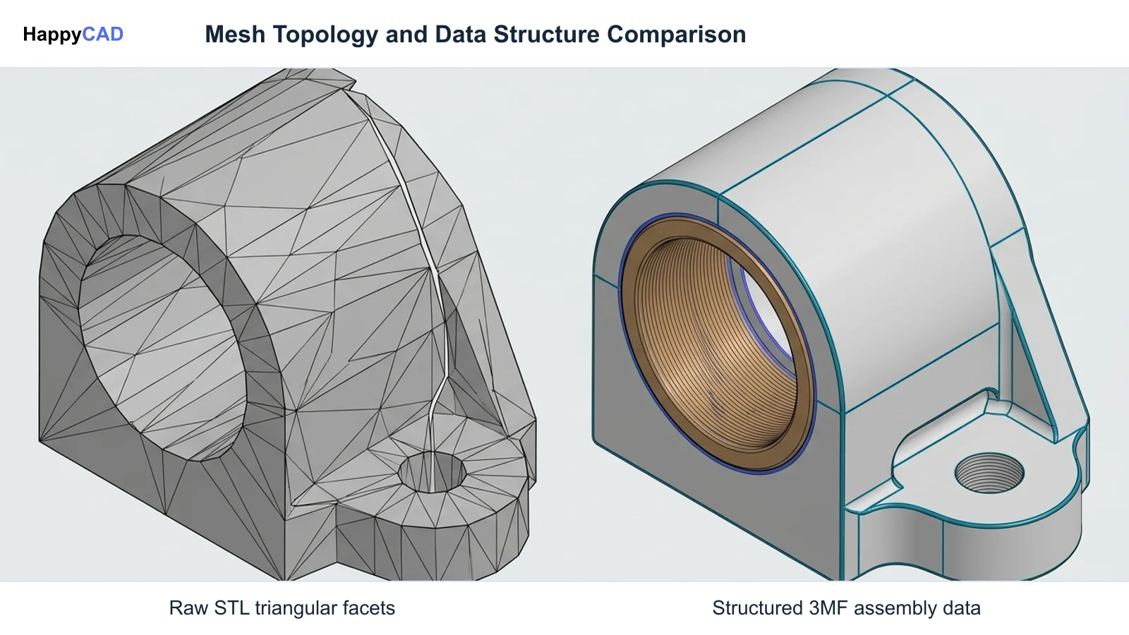
Although both formats approximate 3D geometry using surface tessellation, their underlying digital architectures differ fundamentally. STL provides an unindexed list of planar triangles, whereas 3MF functions as a structured archive built on Open Packaging Conventions (OPC).
The following engineering breakdown outlines how both formats handle critical parameters from mesh topology to manufacturing metadata.[2][3][4][5][6][8]
| Factor | 3MF | STL |
|---|---|---|
| Data Architecture | Compressed ZIP archive containing structured XML payloads | Sequential list of planar triangular facets (ASCII or binary)[2][5] |
| Unit Specification | Explicitly defined in file headers (e.g., millimeter, micron, inch) | Not stored; sender and receiver need an agreed unit convention[3][4] |
| Topological Integrity | Enforces manifold topology and shared vertex indexing | No topological connectivity; prone to cracks, leaks, and flipped normals[3] |
| Assembly Structure | Maintains discrete component IDs, instances, and transform matrices | Flattens assemblies into a single combined, unreferenced mesh[2] |
| Color and Materials | Native support for per-vertex colors, textures, and material densities | No standardized color, texture, or physical property storage[5][7] |
| Slicing Integration | Supports pre-calculated slice polylines directly from CAD | Not stored; the slicer derives layers from the mesh geometry[8] |
| CNC Stock Simulation | Limited native adoption in legacy CAM simulation tools | Standard format for in-process stock models and rest-machining meshes[6] |
3MF: Pros and Cons
The 3D Manufacturing Format (3MF) was created by an industry consortium to replace the archaic limitations of STL. It organizes geometry, appearance, and machine instructions into an extensible, compressed container.
While 3MF provides superior data fidelity, implementation consistency can still vary depending on how specific CAD software packages export its optional extensions.[1][2][5][7][8]
Advantages
- Preserves explicit units, avoiding 25.4-times metric/inch scaling errors during import.
- Maintains multi-body assemblies, component instances, and spatial transform matrices.
- Supports rich production metadata including materials, full-color textures, and slice polylines.
- Compact file footprint due to native ZIP compression and shared vertex indexing.
Limitations
- Inconsistent extension support across different CAD packages and legacy slicers.
- Limited adoption across legacy CNC CAM software for basic stock verification.
STL: Pros and Cons
Stereolithography (STL) has been the de facto standard across rapid prototyping and manufacturing since the late 1980s. Its sheer simplicity allows almost any 3D package to parse its triangle facet list.
STL can represent a valid closed mesh, but the format does not establish units, design intent, or geometric validity. Check those requirements after import and repair the geometry only when the checks reveal a defect.[1][3][4][6]
Advantages
- Universal compatibility across virtually every 3D printer, slicer, and CAD/CAM program.
- Reliable, lightweight format for passing raw in-process stock simulation bodies in CNC CAM.
Limitations
- Lacks unit definitions, frequently triggering incorrect scale assumptions during ingestion.
- Does not enforce topological connectivity, creating non-manifold edges, gaps, and inverted normals.
- Strips away assembly hierarchy, treating multi-part builds as single amorphous meshes.
Which Fits Your Workflow
Matching 3MF or STL to your engineering process requires evaluating whether your downstream equipment needs comprehensive assembly metadata or just raw spatial boundaries. Different stages of manufacturing impose distinct digital data requirements.[2][5][6][7][8]
Modern Additive Production and Nested Trays
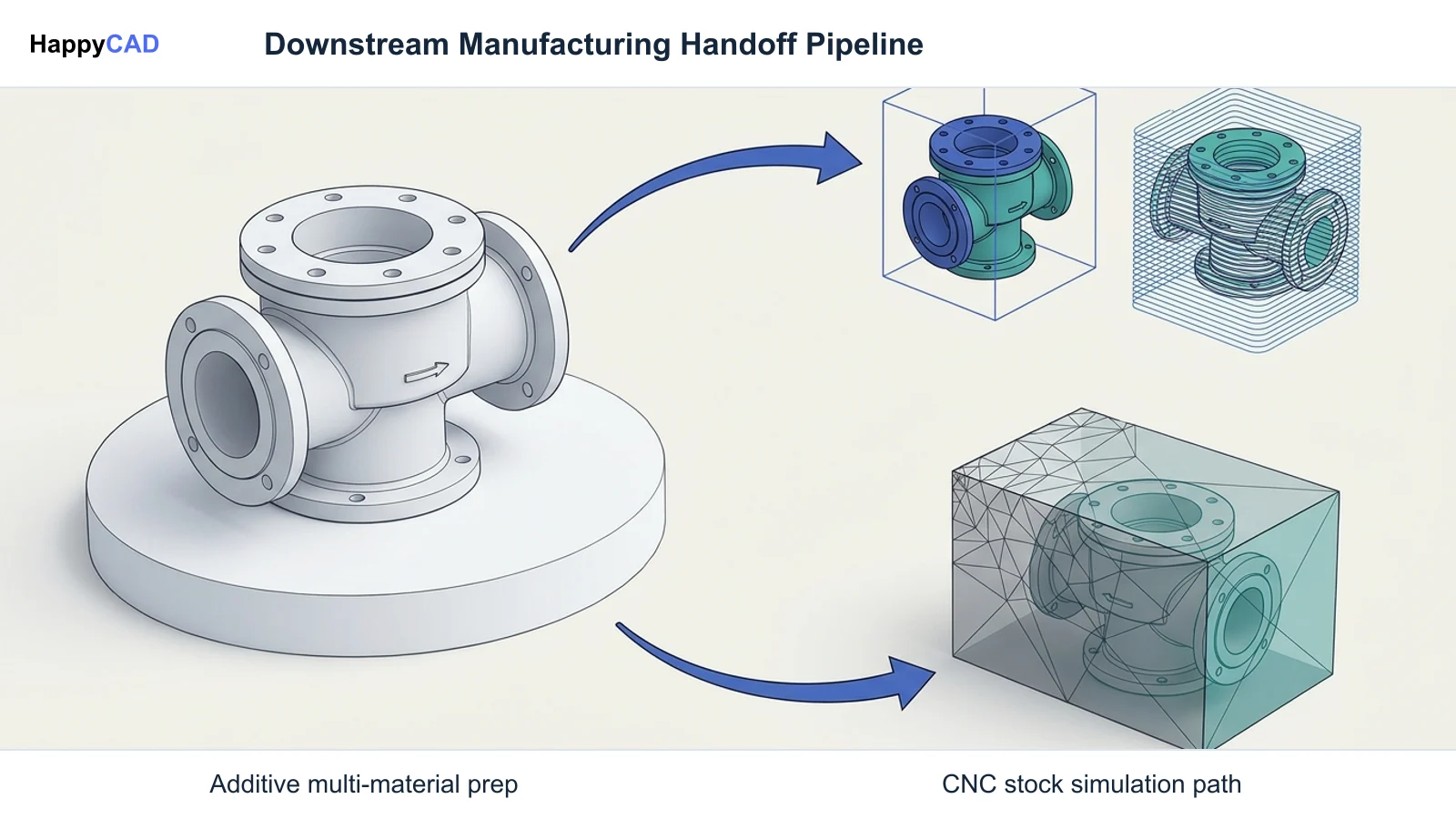
For industrial additive manufacturing platforms such as HP Multi Jet Fusion, Stratasys PolyJet, and Laser Powder Bed Fusion (LPBF), 3MF is the clear standard. These processes often demand multi-material printing, variable color assignments, or nested trays of distinct components.
Exporting to 3MF allows components of an assembly to maintain discrete IDs, relative transform matrices, and material properties. Tools like Ultimaker Cura and Stratasys GrabCAD Print read these extensions directly. In platforms like SOLIDWORKS, users can even export native slicing polylines directly inside the 3MF package, retaining CAD-level precision without forcing the slicer to recalculate slices from coarse meshes.[2][5][7][8]
CNC Machining Simulation and Rest Machining
In subtractive machining environments, the requirements shift from part interior properties to simple boundary verification. As documented in Autodesk Fusion workflows, STL remains widely used to pass in-process stock simulation bodies between setups.
When verifying toolpaths or calculating rest-machining operations, CAM systems only need the visual external boundary of the remaining stock. Color maps, assembly transforms, and advanced metadata are unutilized, making binary STL a functional and universally accepted choice for raw mesh handoffs.[6]
Making and Verifying the Decision
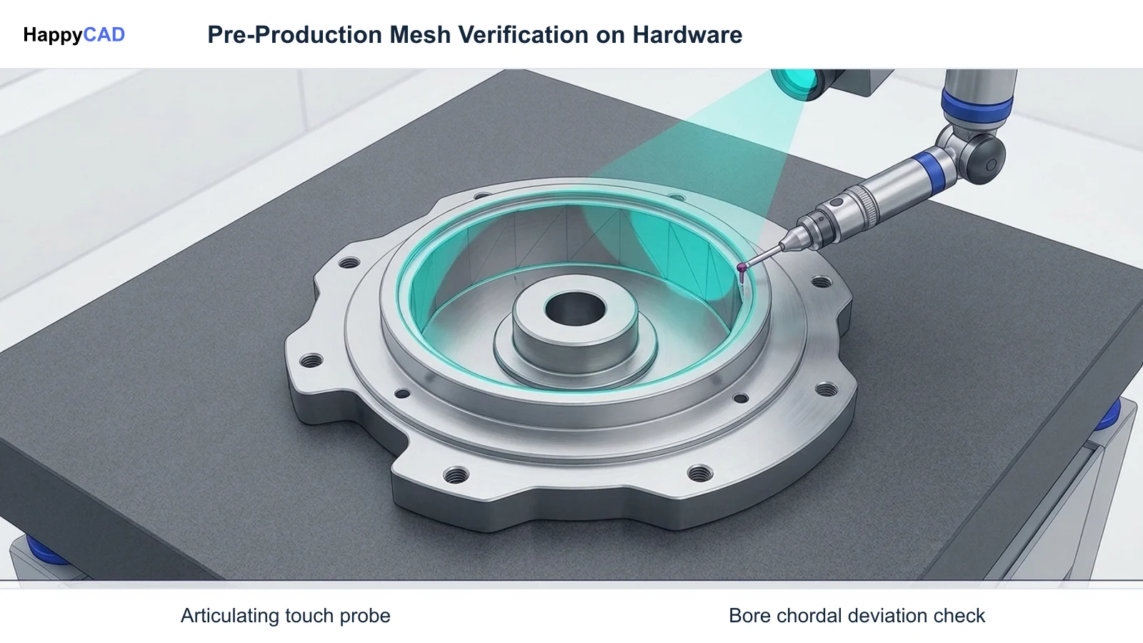
After choosing the export format, check the imported dimensions, scale, orientation, and mesh validity against the design requirements. Use technical drawings where the project requires them. File-format selection alone does not verify tolerances or manufacturing suitability.
Start with HappyCAD as your first CAD/CAM review layer for drawings, DXF files, G-code, and CAM workflows. Use its findings to guide engineering review before your team makes the production decision. HappyCAD assists engineers with GD&T drawing review, helps identify duplicate geometry, open contours, and dimension issues in DXF files, and helps explain G-code and review proposed modifications.
Regardless of whether your facility uses 3MF containers or legacy STL meshes, manufacturing engineers and machine operators retain responsibility for final production decisions, machine setup verification, and physical quality assurance.[2][3][4]
Frequently Asked Questions
Why do STL files often import at the wrong scale in slicing software?
STL does not declare units. Agree on the intended unit convention and check the imported dimensions. Interpreting inch-valued coordinates as millimeters, or the reverse, creates a factor-of-25.4 scale mismatch.[3][4]
Can 3MF files store CAD-generated slicing data?
Yes. Certain CAD platforms, such as SOLIDWORKS, provide slicing data export features that calculate polylines directly against the native mathematical model, embedding layer heights and edges directly into the 3MF container.[8]
Why is STL still preferred for CNC rest-machining stock models?
CAM software programs like Autodesk Fusion frequently export in-process stock bodies as STL files because stock simulation only requires basic boundary meshes, where units and assembly hierarchies are already locked within the CAM session.[6]
Does 3MF export behave identically across all CAD platforms?
No. While the 3MF Consortium maintains rigorous core specifications, individual CAD packages implement optional extensions differently, meaning features like materials, custom support structures, or slice polylines may require explicit configuration.[2][5]
References
Sources
Documentation and technical references for this article.
Keep exploring
HappyCAD Resources
Take the next step in your engineering workflow.
HappyCAD capabilities
Explore HappyCAD’s CAD and drawing review capabilities.
Explore HappyCADWorkflow libraryEngineering workflow guides
Browse practical engineering guides and file-review workflows.
Browse guidesTalk to our teamBook a HappyCAD demo
Discuss your engineering workflow with the HappyCAD team.
Book a demoBring a Second Review to Your Workflow
Explore how HappyCAD can streamline your engineering review process across drawings, DXF files, and CAM setups.
Try HappyCAD